Thyristor
- or as it is also known the silicon controlled rectifier (SCR)
Thyristors or silicon controlled rectifiers (SCR) are find
many uses in electronics, and in particular for power control. Indeed thyristors
have been called the workhorse of high power electronics. Here the silicon
controlled rectifiers are able to switch large levels of power are used in a
wide variety of different applications. Thyristors even finds uses in low power
electronics where they are able to find applications in many circuits from light
dimmers to power supply over voltage protection.
Discovery
The idea for the thyristor or silicon controlled rectifier (SCR) was first
described by Shockley in 1950. It was referred to as a bipolar transistor with a
p-n hook-collector. The mechanism for the operation of the thyristor was
analysed further in 1952 by Ebers. Then in 1956 Moll investigated the switching
mechanism of the thyristor. Development continued and more was learned about the
device such that the first silicon controlled rectifiers became available in the
early 1960s where it started to gain a significant level of popularity for power
switching.
Structure
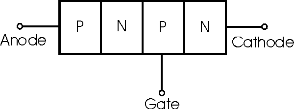
The thyristor consists of a four layer p-n-p-n structure with the outer layers
are referred to as the anode (n-type) and cathode (n-type). The control terminal
of the SCR is named the gate and it is connected to the p-type layer located
next to the cathode.

Structure of a thyristor or silicon controlled
rectifier (SCR)
The level of doping varies between the different layers of
the thyristor. The cathode is the most heavily doped. The gate and anode are the
next heavily doped. The lowest doping level is within the central n type layer.
This is also thicker than the other layers and these two factors enable a large
blocking voltage to be supported. Thinner layers would mean that the device
would break down at lower voltages.
In view of the very high currents and power levels that some
thyristors are used to switch, thermal considerations are of paramount
importance. The anode of the SCR or silicon controlled rectifier is usually
bonded to the package since the gate terminal is near the cathode and needs to
be connected separately. This is accomplished in such a way that heat is removed
from the silicon to the package. Apart from the internal considerations, the
external heat-sinking considerations for the thyristor must be carefully
implemented otherwise the device may overheat and fail.
Thyristors are usually manufactured from silicon. There are
two main reasons for this. One is the voltage, current and thermal handling
properties of silicon enable it to meet the requirements of the power industry,
and secondly silicon technology is well developed and very cheap to use.
Operation
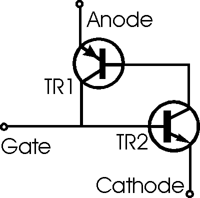
In operation the SCR may be considered as two back to back transistors. The
transistor with its emitter connected to the cathode of the thyristor is a n-p-n
device whereas the transistor with its emitter connected to the anode of the SCR
is a p-n-p variety. The gate is connected to the base of the n-p-n transistor.

Equivalent circuit of a thyristor or silicon
controlled rectifier (SCR)
This arrangement forms a positive feedback loop within the
thyristor. The output of one transistor fed to the input of the second. In turn
the output of the second transistor is fed back to the input of the first. As a
result it can be seen that the total current gain of the device exceeds one.
This means that when a current starts to flow, it quickly builds up until both
transistors are fully turned on or saturated.
When a voltage is applied across a thyristor no current flows
because neither transistor is conducting. As a result there is no complete path
across the device. If a small current is passed through the gate electrode, this
will turn "on" the transistor TR2. When this occurs it will cause the collector
of TR2 to fall towards the voltage on the emitter, i.e. the cathode of the whole
device. When this occurs it will cause current to flow through the base of TR1
and turn this transistor "on". Again this will now try to pull the voltage on
the collector of TR1 towards its emitter voltage. This will cause current to
flow in the emitter of TR2, causing its "on" state to be maintained. In this way
it only requires a small trigger pulse on the gate to turn the thyristor on.
Once switched on, the thyristor can only be turned off by removing the supply
voltage.
|

