Radio receiver frequency modulation (FM) demodulation
- overview or tutorial of the basics of frequency modulation or FM
demodulation using Foster-Seeley, ratio, phase locked loop (pll) and quadrature
detectors or demodulators.
Frequency modulation is widely used in radio communications
and broadcasting, particularly on frequencies above 30 MHz. It offers many
advantages, particularly in mobile radio applications where its resistance to
fading and interference is a great advantage. It is also widely used for
broadcasting on VHF frequencies where it is able to provide a medium for high
quality audio transmissions.
In view of its widespread use receivers need to be able to
demodulate these transmissions. There is a wide variety of different techniques
and circuits that can be sued including the Foster-Seeley, and ratio detectors
using discreet components, and where integrated circuits are used the phase
locked loop and quadrature detectors are more widely used.
What is FM?
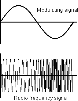
As the name suggests frequency modulation uses changes in
frequency to carry the sound or other information that is required to be placed
onto the carrier. As shown in Figure 1 it can be seen that as the modulating or
base band signal voltage varies, so the frequency of the signal changes in line
with it. This type of modulation brings several advantages with it. The first is
associated with interference reduction. Much interference appears in the form of
amplitude variations and it is quite easy to make FM receivers insensitive to
amplitude variations and accordingly this brings about a reduction in the levels
of interference. In a similar way fading and other strength variations in the
signal have little effect. This can be particularly useful for mobile
applications where charges in location as the vehicle moves can bring about
significant signal strength changes. A further advantage of FM is that the RF
amplifiers in transmitters do not need to be linear. When using amplitude
modulation or its derivatives, any amplifier after the modulator must be linear
otherwise distortion is introduced. For FM more efficient class C amplifiers may
be used as the level of the signal remains constant and only the frequency
varies.
Frequency modulating a signal
Wide band and Narrow band
When a signal is frequency modulated, the carrier shifts in
frequency in line with the modulation. This is called the deviation. In the same
way that the modulation level can be varied for an amplitude modulated signal,
the same is true for a frequency modulated one, although there is not a maximum
or 100% modulation level as in the case of AM.
The level of modulation is governed by a number of factors.
The bandwidth that is available is one. It is also found that signals with a
large deviation are able to support higher quality transmissions although they
naturally occupy a greater bandwidth. As a result of these conflicting
requirements different levels of deviation are used according to the application
that is used.
Those with low levels of deviation are called narrow band
frequency modulation (NBFM) and typically levels of +/- 3 kHz or more are used
dependent upon the bandwidth available. Generally NBFM is used for point to
point communications. Much higher levels of deviation are used for broadcasting.
This is called wide band FM (WBFM) and for broadcasting deviation of +/- 75 kHz
is used.
Receiving FM
In order to be able to receive FM a receiver must be
sensitive to the frequency variations of the incoming signals. As already
mentioned these may be wide or narrow band. However the set is made insensitive
to the amplitude variations. This is achieved by having a high gain IF
amplifier. Here the signals are amplified to such a degree that the amplifier
runs into limiting. In this way any amplitude variations are removed.
In order to be able to convert the frequency variations into
voltage variations, the demodulator must be frequency dependent. The ideal
response is a perfectly linear voltage to frequency characteristic. Here it can
be seen that the centre frequency is in the middle of the response curve and
this is where the un-modulated carrier would be located when the receiver is
correctly tuned into the signal. In other words there would be no offset DC
voltage present.
The ideal response is not achievable because all systems have
a finite bandwidth and as a result a response curve known as an "S" curve is
obtained. Outside the badwidth of the system, the response falls, as would be
expected. It can be seen that the frequency variations of the signal are
converted into voltage variations which can be amplified by an audio amplifier
before being passed into headphones, a loudspeaker, or passed into other
electronic circuitry for the appropriate processing.
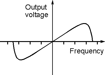
Characteristic "S" curve of an FM demodulator
To enable the best detection to take place the signal should
be centred about the middle of the curve. If it moves off too far then the
characteristic becomes less linear and higher levels of distortion result. Often
the linear region is designed to extend well beyond the bandwidth of a signal so
that this does not occur. In this way the optimum linearity is achieved.
Typically the bandwidth of a circuit for receiving VHF FM broadcasts may be
about 1 MHz whereas the signal is only 200 kHz wide.
FM demodulators
There are a number of circuits that can be used to demodulate
FM. Each type has its own advantages and disadvantages, some being used when
receivers used discrete components, and others now that ICs are widely used.
Slope detection
The very simplest form of FM demodulation is known as slope
detection or demodulation. It simply uses a tuned circuit that is tuned to a
frequency slightly offset from the carrier of the signal. As the frequency of
the signal varies up and down in frequency according to its modulation, so the
signal moves up and down the slope of the tuned circuit. This causes the
amplitude of the signal to vary in line with the frequency variations. In fact
at this point the signal has both frequency and amplitude variations. The final
stage in the process is to demodulate the amplitude modulation and this can be
achieved using a simple diode circuit. One of the most obvious disadvantages of
this simple approach is the fact that both amplitude and frequency variations in
the incoming signal appear at the output. However the amplitude variations can
be removed by placing a limiter before the detector. Additionally the circuit is
not particularly efficient as it operates down the slope of the tuned circuit.
It is also unlikely to be particularly linear, especially if it is operated
close to the resonant point to minimise the signal loss.
Ratio and Foster-Seeley FM detectors
When circuits employing discrete components were more widely
sued, the Ratio and Foster-Seeley detectors were widely used. Of these the ratio
detector was the most popular as it offers a better level of amplitude
modulation rejection of amplitude modulation. This enables it to provide a
greater level of noise immunity as most noise is amplitude noise, and it also
enables the circuit to operate satisfactorily with lower levels of limiting in
the preceding IF stages of the receiver.
The operation of the ratio detector centres around a
frequency sensitive phase shift network with a transformer and the diodes that
are effectively in series with one another. When a steady carrier is applied to
the circuit the diodes act to produce a steady voltage across the resistors R1
and R2, and the capacitor C3 charges up as a result.
The transformer enables the circuit to detect changes in the
frequency of the incoming signal. It has three windings. The primary and
secondary act in the normal way to produce a signal at the output. The third
winding is un-tuned and the coupling between the primary and the third winding
is very tight, and this means that the phasing between signals in these two
windings is the same.
The primary and secondary windings are tuned and lightly
coupled. This means that there is a phase difference of 90 degrees between the
signals in these windings at the centre frequency. If the signal moves away from
the centre frequency the phase difference will change. In turn the phase
difference between the secondary and third windings also varies. When this
occurs the voltage will subtract from one side of the secondary and add to the
other causing an imbalance across the resistors R1 and R2. As a result this
causes a current to flow in the third winding and the modulation to appear at
the output.
The capacitors C1 and C2 filter any remaining RF signal which
may appear across the resistors. The capacitor C4 and R3 also act as filters
ensuring no RF reaches the audio section of the receiver.
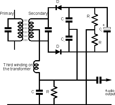
The ratio detector
The Foster Seeley detector has many similarities to the ratio
detector. The circuit topology looks very similar, having a transformer and a
pair of diodes, but there is no third winding and instead a choke is used.
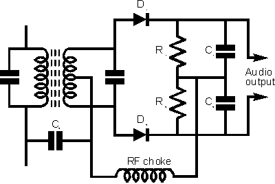
The Foster-Seeley detector
Like the ratio detector, the Foster-Seeley circuit operates
using a phase difference between signals. To obtain the different phased signals
a connection is made to the primary side of the transformer using a capacitor,
and this is taken to the centre tap of the transformer. This gives a signal that
is 90 degrees out of phase.
When an un-modulated carrier is applied at the centre
frequency, both diodes conduct, to produce equal and opposite voltages across
their respective load resistors. These voltages cancel each one another out at
the output so that no voltage is present. As the carrier moves off to one side
of the centre frequency the balance condition is destroyed, and one diode
conducts more than the other. This results in the voltage across one of the
resistors being larger than the other, and a resulting voltage at the output
corresponding to the modulation on the incoming signal.
The choke is required in the circuit to ensure that no RF
signals appear at the output. The capacitors C1 and C2 provide a similar
filtering function.
Both the ratio and Foster-Seeley detectors are expensive to
manufacture. Wound components like coils are not easy to produce to the required
specification and therefore they are comparatively costly. Accordingly these
circuits are rarely used in modern equipment.
Quadrature FM detector
Another form of FM detector or demodulator that can be these
days is called the quadrature detector. It lends itself to use with integrated
circuits and as a result it is in widespread use. It has the advantage over the
ratio and Foster-Seeley detectors that it only requires a simple tuned circuit.
For the quadrature detector, the signal is split into two
components. One passes through a network that provides a basic 90 degree phase
shift, plus an element of phase shift dependent upon the deviation and into one
port of a mixer. The other is passed straight into another port of the mixer.
The output from the mixer is proportional to the phase difference between the
two signals, i.e. it acts as a phase detector and produces a voltage output that
is proportional to the phase difference and hence to the level of deviation on
the signal.
The detector is able to operate with relatively low input
levels, typically down to levels of around 100 microvolts and it is very easy to
set up requiring only the phase shift network to be tuned to the centre
frequency of the expected signal. It also provides good linearity enabling very
low levels of distortion to be achieved.
Often the analogue multiplier is replaced by a logic AND
gate. The input signal is hard limited to produce a variable frequency pulse
waveform. The operation of the circuit is fundamentally the same, but it is
known as a coincidence detector. Also the output of the AND gate has an
integrator to "average" the output waveform to provide the required audio
output, otherwise it would consist of a series of square wave pulses.
Phase locked loop (PLL)
Another popular form of FM demodulator comes in the form of a
phase locked loop. Like the quadrature detector, phase locked loops do not need
to use a coil, and therefore they make a very cost effective form of
demodulator.
The way in which they operate is very simple. The loop
consists of a phase detector into which the incoming signal is passed, along
with the output from the voltage controlled oscillator (VCO) contained within
the phase locked loop. The output from the phase detector is passed into a loop
filter and then sued as the control voltage for the VCO.
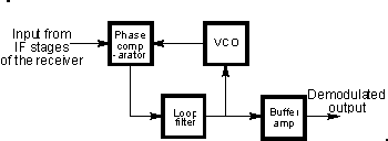
Phase locked loop (PLL) FM demodulator
With no modulation applied and the carrier in the centre
position of the pass-band the voltage on the tune line to the VCO is set to the
mid position. However if the carrier deviates in frequency, the loop will try to
keep the loop in lock. For this to happen the VCO frequency must follow the
incoming signal, and for this to occur the tune line voltage must vary.
Monitoring the tune line shows that the variations in voltage correspond to the
modulation applied to the signal. By amplifying the variations in voltage on the
tune line it is possible to generate the demodulated signal.
It is found that the linearity of this type of detector is
governed by the voltage to frequency characteristic of the VCO. As it normally
only swings over a small portion of its bandwidth, and the characteristic can be
made relatively linear, the distortion levels from phase locked loop
demodulators are normally very low.
|


