Averaging Level Control
V essels known as surge tanks are
frequently located between process units for the express purpose of smoothing
flow variations. However, there is a tendency in modern plants to minimize this
inventory and, in some cases, these vessels have been eliminated. Even when
present they are not always properly controlled, passing disturbances through
rather than attenuating them, and even producing cyclic flow variations.

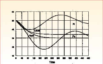
Fig. 1. A vessel having a time constant (holdup) of 100 min has its level
and outflow initially at 50%.
Unfortunately, in the presence of integral action, this destabilizes the
loop, producing long-term cycling. The problem is illustrated in Fig. 1.
Liquid level is ordinarily easy to control by using a conventional
proportional-plus-integral (PI) controller. Using a tight proportional band
(high gain) can keep level near setpoint, but this can cause the manipulated
outflow to vary even more than the inflow to the vessel. Short-term variations
in outflow can be reduced by widening the proportional band (reducing the
proportional gain) of the controller.
Here, a vessel having a time constant (holdup) of 100 min has its level and
outflow initially at 50%. At time zero, inflow to the vessel suddenly drops to
30%, causing level and outflow to begin falling. Integral action in the
controller attempts to restore the level to its setpoint of 50%, but can only do
so by actually reducing outflow below inflow, in this case overshooting the
inflow change by nearly 100%.
This overshoot not only amplifies the upset but also promotes a lightly
damped oscillation of 400-min period that will persist for several cycles. In
this simulation, the level controller had a proportional band of 200% (a gain of
0.5) and an integral time of 20 min.
The figure also shows the level and flow responses to the same upset using a
proportional-lag (P*) controller having a proportional band of 80% and a lag
time constant of 20 min. Note that the resulting variation in outflow is less
than for the PI controller, and that no oscillation results�level and flow both
approach their new steady states exponentially.
The fundamental difference in the final steady states for the two controllers
is that the PI controller will eventually return level to the 50% setpoint,
whereas the P* controller allows the level to change proportionally to the
average flow.
This variation in level is a stumbling block for both engineers and
operators. The latter are accustomed to controlling at setpoint in the steady
state. When this does not happen, the operators assume that the controller is
not functioning properly.
Engineers assume that the optimum level is at the middle of the tank,
allowing the maximum margin for variation in both directions.
In fact, the margin does not have to be the same in both directions for all
flowrates. At maximum inflow, the vessel can be nearly full because there is
little chance of inflow increasing. At zero inflow it can be nearly empty. This
is accomplished by using proportional action with a band of 80%. Outflow will be
zero at 10% level and maximum at 90% level.
However, a true proportional controller, one having an adjustable "manual
reset" bias, must be used. The bias and setpoint may both be set at 50%, or the
setpoint may be positioned at the low-level limit (e.g., 10%) and the bias at
zero. The latter is preferred to avoid expectations associated with a 50%
setpoint.
The lag may be placed on the level input to the controller or in its output.
It is not an essential function, simply providing extra filtering for the flow.
Proportional action is the essential feature of the averaging level controller.
|

