1. Similarity
Hydraulic models may be either true or distorted models. True models
reproduce features of the prototype but at a scale - that is they are
geometrically similar.
2. Geometric similarity
Geometric similarity exists between model and prototype if the ratio of all
corresponding dimensions in the model and prototype are equal.

where lL is the scale factor for
length.
For area

All corresponding angles are the same.
3. Kinematic similarity
Kinematic similarity is the similarity of time as well as geometry. It exists
between model and prototype
- If the paths of moving particles are geometrically similar
- If the rations of the velocities of particles are similar
Some useful ratios are:
Velocity

Acceleration

Discharge

This has the consequence that streamline patterns are the same.
4. Dynamic similarity
Dynamic similarity exists between geometrically and kinematically similar
systems if the ratios of all forces in the model and prototype are the same.
Force ratio

This occurs when the controlling dimensionless group on the right hand side
of the defining equation is the same for model and prototype.
5. Models
When a hydraulic structure is build it undergoes some analysis in the design
stage. Often the structures are too complex for simple mathematical analysis and
a hydraulic model is build. Usually the model is less than full size but it may
be greater. The real structure is known as the prototype. The model is usually
built to an exact geometric scale of the prototype but in some cases - notably
river model - this is not possible. Measurements can be taken from the model and
a suitable scaling law applied to predict the values in the prototype.
To illustrate how these scaling laws can be obtained we will use the
relationship for resistance of a body moving through a fluid.
The resistance, R, is dependent on the following physical properties:
r: ML-3 u: LT-1
l:(length) L m: ML-1T-1
So the defining equation is f (R,
r, u, l, m ) = 0
Thus, m = 5, n = 3 so there are 5-3 = 2 p groups


For the p1 group

Leading to p1 as

For the p2 group

Leading to p1 as

Notice how 1/p2 is the Reynolds number.
We can call this p2a.
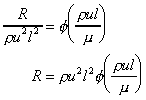
So the defining equation for resistance to motion is
f ( p1 ,
p2a ) = 0
We can write

This equation applies whatever the size of the body i.e. it is applicable to
a to the prototype and a geometrically similar model. Thus for the model

and for the prototype

Dividing these two equations gives

At this point we can go no further unless we make some assumptions. One
common assumption is to assume that the Reynolds number is the same for both the
model and prototype i.e.

This assumption then allows the equation following to be written

Which gives this scaling law for resistance force:

That the Reynolds numbers were the same was an essential assumption for this
analysis. The consequence of this should be explained.


Substituting this into the scaling law for resistance gives

So the force on the prototype can be predicted from measurement of the force
on the model. But only if the fluid in the model is moving with same Reynolds
number as it would in the prototype. That is to say the Rp can be
predicted by

provided that

In this case the model and prototype are dynamically similar.
Formally this occurs when the controlling dimensionless group on the right
hand side of the defining equation is the same for model and prototype. In this
case the controlling dimensionless group is the Reynolds number.
6. Dynamically similar model examples
Example 1
An underwater missile, diameter 2m and length 10m is tested in a water tunnel
to determine the forces acting on the real prototype. A 1/20th scale
model is to be used. If the maximum allowable speed of the prototype missile is
10 m/s, what should be the speed of the water in the tunnel to achieve dynamic
similarity?
For dynamic similarity the Reynolds number of the model and prototype must be
equal:

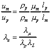
So the model velocity should be

As both the model and prototype are in water then, mm
= mp and rm
= rp so

Note that this is a very high velocity. This is one reason why model
tests are not always done at exactly equal Reynolds numbers. Some relaxation of
the equivalence requirement is often acceptable when the Reynolds number is
high. Using a wind tunnel may have been possible in this example. If this were
the case then the appropriate values of the r
and m ratios need to be used in the above
equation.
Example 2
A model aeroplane is built at 1/10 scale and is to be tested in a wind tunnel
operating at a pressure of 20 times atmospheric. The aeroplane will fly at
500km/h. At what speed should the wind tunnel operate to give dynamic similarity
between the model and prototype? If the drag measure on the model is 337.5 N
what will be the drag on the plane?
From earlier we derived the equation for resistance on a body moving through
air:

For dynamic similarity Rem = Rep, so

The value of m does not change much with
pressure so mm = mp
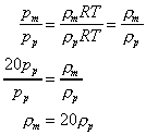
The equation of state for an ideal gas is p = rRT
. As temperature is the same then the density of the air in the model can be
obtained from

So the model velocity is found to be

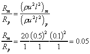
The ratio of forces is found from

So the drag force on the prototype will be

7. Models with free surfaces - rivers, estuaries
etc.
When modelling rivers and other fluid with free surfaces the effect of
gravity becomes important and the major governing non-dimensional number becomes
the Froude (Fn) number. The resistance to motion formula above would then be
derived with g as an extra dependent variables to give an extra
p group. So the defining equation is:
f (R, r, u, l,
m, g ) = 0
From which dimensional analysis gives:

Generally the prototype will have a very large Reynolds number, in which case
slight variation in Re causes little effect on the behaviour of the problem.
Unfortunately models are sometimes so small and the Reynolds numbers are large
and the viscous effects take effect. This situation should be avoided to achieve
correct results. Solutions to this problem would be to increase the size of the
model - or more difficult - to change the fluid (i.e. change the viscosity of
the fluid) to reduce the Re.
8. Geometric distortion in river models
When river and estuary models are to be built, considerable problems must be
addressed. It is very difficult to choose a suitable scale for the model and to
keep geometric similarity. A model which has a suitable depth of flow will often
be far to big - take up too much floor space. Reducing the size and retaining
geometric similarity can give tiny depth where viscous force come into play.
These result in the following problems:
- accurate depths and depth changes become very difficult to measure;
- the bed roughness of the channel becomes impracticably small;
- laminar flow may result - (turbulent flow is normal in river
hydraulics.)
The solution often adopted to overcome these problems is to abandon strict
geometric similarity by having different scales in the horizontal and the
vertical. Typical scales are 1/100 in the vertical and between 1/200 and 1/500
in the horizontal. Good overall flow patterns and discharge characteristics can
be produced by this technique, however local detail of flow is not well modelled.
In these model the Froude number (u2/d) is used as the
dominant non-dimensional number. Equivalence in Froude numbers can be achieved
between model and prototype even for distorted models. To address the roughness
problem artificially high surface roughness of wire mesh or small blocks is
usually used.
|

