| Flip-Flops |
Flip-Flops
Why Study Flip-Flops?
There are some circuits that are not quite
as straight forward as the gate circuits we have discussed in earlier lessons.
However, you still need to learn about circuits that can store and remember
information. They're the kind of circuits that are used in computers to store
program information - RAM memory.
In this lesson we'll look at the background
for those kinds of memory circuits. Our goal is the following.
 Given a flip-flop circuit,
 Determine
how the circuit will behave for a sequence of inputs. Determine
how the circuit will behave for a sequence of inputs.
 Be able to use a flip-flop to store a single bit.
Basic Circuit
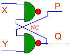
Here's a basic circuit that involves just
two NAND gates. There are two inputs to this circuit, X and Y. Can you
generate a truth table for this circuit?

- Note that there is no
connection where the two wires running from the output back to the input
cross.
Let's address that issue of the truth table.
Here is a truth table for you to fill in. (Print this web page if you want to
work on it.)
Let's review what you know about this
circuit. We can focus on what happens when X= 0, and Y = 0, the first entry in
the truth table above.
- If X = 0, then P = 1. We
know that if either input to a NAND gate is 0, the output is 1.
- Now. try to take advantage of
the knowledge that P = 1. If P = 1 AND Y = 0, then Q = 1. It doesn't
matter what P is, as long as Y = 0, Q will be 1.
- That gives us the first entry
in the truth table above. Here's the truth table with what we have figured
out so far.
| X
|
Y
|
P
|
Q
|
| 0
|
0
|
1
|
1
|
| 0
|
1
|
|
|
| 1
|
0
|
|
|
| 1
|
1
|
|
|
Now, let's address the second
entry in the truth table. In that situation, X = 0, and Y = 1.
- If X = 0, then P = 1. We
know that if either input to a NAND gate is 0, the output is 1. That's the
same as before.
- Now. try to take advantage of
the knowledge that P = 1. If P = 1 AND Y = 1, then Q = 0.
- That gives us the second
entry in the truth table above. Here's the truth table with what we have
figured out so far.
| X
|
Y
|
P
|
Q
|
| 0
|
0
|
1
|
1
|
| 0
|
1
|
1
|
0
|
| 1
|
0
|
|
|
| 1
|
1
|
|
|
Next, let's address the third
entry in the truth table. In that situation, X = 1, and Y = 0.
- If Y = 0, then Q = 1. We
know that if either input to a NAND gate is 0, the output is 1. That's the
same as before. However, this time, we take advantage of knowing that Y =
0. Before, it was X that was equal to zero, but X = 1 here and it doesn't
help us get started.
- Now. try to take advantage of
the knowledge that Q = 1. If Q = 1 AND X = 1, then P = 0.
- That gives us the third entry
in the truth table above. Here's the truth table with what we have figured
out so far.
| X
|
Y
|
P
|
Q
|
| 0
|
0
|
1
|
1
|
| 0
|
1
|
1
|
0
|
| 1
|
0
|
0
|
1
|
| 1
|
1
|
|
|
Finally, we have the case where X = 1 and Y =
1.
- If X = 1, then we need to
know Q to determine P.
- If Y = 1, then we need to
know P to determine Q.
- We are stuck! There is no
obvious way to proceed!
There is one way to proceed. We could just
assume that P = 1, for example. Let's try that.
- If Y = 1, and P = 1, then we
know that Q = 0.
- If we know that Q = 0, it is
an input to the top NAND gate, so the output there is 1. Thus, P = 1.
That's what we assumed to start with, so we don't get a contradiction.
- All is copasetic! Or is it?
- Here is the truth table.
| X
|
Y
|
P
|
Q
|
| 0
|
0
|
1
|
1
|
| 0
|
1
|
1
|
0
|
| 1
|
0
|
0
|
1
|
| 1
|
1
|
1
|
0
|
This is interesting, but we need to note the
following.
- This result is not at all
intuitive.
- The circuit is symmetric.
- If we have symmetric
inputs (X = 1, Y = 1), we should have symmetric outputs.
- Instead, we seem to have
shown that P = 1 and Q = 0. That's not at all symmetric, and it it
bothersome.
- We got to the result by
making an unsymmetrical assumption. We assumed P = 1.
What if we made the opposite assumption?
Let's assume P = 0.
- If P = 0, then Q = 1 since P
is an input to the bottom NAND gate.
- If we know that Q = 1, it is
an input to the top NAND gate, so the output there is P = 0 since the other
input to the top gate, X, is also 1.
- But, P = 0 is what we assumed
to start all this. Again, we do not get a contradiction, so everything
seems OK.
- Here is the truth table for
this situation.
| X
|
Y
|
P
|
Q
|
| 0
|
0
|
1
|
1
|
| 0
|
1
|
1
|
0
|
| 1
|
0
|
0
|
1
|
| 1
|
1
|
0
|
1
|
Now, we can't have it both ways. This truth
table summarizes what we have found.
| X
|
Y
|
P
|
Q
|
| 0
|
0
|
1
|
1
|
| 0
|
1
|
1
|
0
|
| 1
|
0
|
0
|
1
|
| 1
|
1
|
|
|
There's something decidedly peculiar
here. The output has to be one or the other of these two cases. Which is it?
But, there's a related question.
- When you were little and went
to the playground, when you walked up to the see-saw, which direction did
the see-saw tilt? Or did you call it a teeter-totter?
- Like the
see-saw/teeter-totter, this circuit depends upon what went on before.
- It can exist in either
state. The see-saw can tilt in either direction. Which state you find
depends upon history.
- This circuit has a name
with that same-consonant-different-vowel property. It's called a
flip-flop.
Now, let's imagine that we do the following.
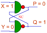
- Let us assume that we input X
= 1 and Y = 0. Then, the output will be P = 0, Q = 1. Here is the
flip-flop in that state

- Then, consider what happens
when Y changes from 0 to 1. Since P = 0, Q will not change when Y changes.
It only takes one zero input to keep the output of a NAND gate at one. That
means that the output does not change when Y changes to 1.
We can reverse the initial inputs.
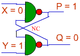
- Let us assume that we input X
= 0 and Y = 1. Then, the output will be P = 1, Q = 0. Here is the
flip-flop in that state

- Now, consider what happens
when X changes from 1 to 0. Since Q = 0, P will not change when X changes.
It only takes one zero input to keep the output of a NAND gate at one. That
means that the output does not change when X changes to 1.
Some observations:
- This circuit is a prototype
of a memory element. It can store and remember one bit of information.
- Before it's a good memory
element, it will need a little work.
- The method we used to
determine possible states in the flip-flop, including especially the case of
inputs with two possible stable states, is the method of contradiction.
Here's a simulation of the basic flip-flop.
Check out the truth table for the circuit and be sure that you understand how it
works. There will be a question or two after the simulation.
|

