| Introduction to Electrical Measurements |
An Introduction To
Electrical Measurements
Electrical measurements often come down to
either measuring current or measuring voltage. Even if you are measuring
frequency, you will be measuring the frequency of a current signal or a voltage
signal and you will need to know how to measure either voltage or current.
In
this short lesson, we will examine those two measurements - starting with
measuring voltage. However, first we should note a few common characteristics
of the meters you use for those measurements.
Many times you will use a digital
multimeter - a DMM - to measure either voltage or current. Actually, a DMM will
also usually measure frequency (of a voltage signal) and resistance. You should
note the following about typical DMMs.
Polarity is important.
Usually the terminals of the DMM will be coded to indicate polarity. Often
that polarity is indicated by a red terminal (positive) and a black terminal
(negative). In other cases, the polarity could be indicated by printed
notes on the terminals. Often one of the terminals on
the DMM may be connected to the ground. That would normally be the black
terminal, or it may be indicated with a ground symbol.
With that in mind, let's get on to measuring voltage.
Measuring Voltage
Voltage is one of the most common
quantities measured. That's because many other variables - like temperature,
for example - are measured by generating a voltage with a sensor. So, even if
you want to measure temperature you might end up having to measure a voltage and
convert that reading into the temperature reading you wanted.
Voltage is measured with a
voltmeter. However, digital multimeters (DMMs) -
which can function as voltmeters - often have considerably more capability and
can measure current, resistance and frequency. And, there are other instruments
- like oscilloscopes - that measure voltage and should be thought of as
voltmeters. No matter what the instrument is, if it measures voltage you have
to treat the instrument as a voltmeter.
When you measure voltage you have to
remember that voltage is an across variable. When
you measure voltage you have to connect the voltmeter to the two points in a
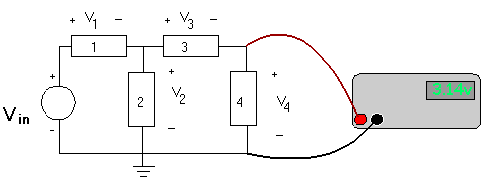
circuit where you want to measure voltage. Here is a circuit with a voltmeter
connected to measure the voltage across element #4.

Note the following about this measurement.
Notice that the voltmeter
measures the voltage across element #4, +V4. (And, the
plus sign is important. Remember the polarity issue.) Notice the polarity
definitions for V4, and notice how the red terminal is
connected to the "+" end of element #4. If you reversed the leads, by
connecting the red lead to the "-" terminal on element #4 and the black lead
to the "+" end of element #4, you would be measuring -V4.
And, remember this as well.
When you measure voltage, the
voltmeter should not disturb the circuit where you are attempting to measure
the voltage. In the circuit above, that disturbance is the current drawn by
the voltmeter. You want that current to be as close to zero as it can
possibly be. That means that you need to have the resistance of the
voltmeter as large as possible. There's more discussion of that effect in
the
lesson on measuring voltage. Ideally, the resistance of a voltmeter
would be infinite.
Measuring Current
Current is measured
with an ammeter.
While voltage is a more common measurement, it is often necessary to measure
current. When measuring current, it is important to remember that
current is a flow variable.
Current flows through electrical elements, and if you want to measure current
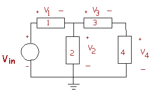
you have to get it to flow through the ammeter. Here's the same circuit we used
in the example above. Consider what we would have to do to measure the current
flowing through element #4.

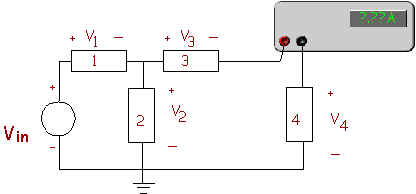
If we want to measure the current through element
#4, we have to get that current to flow through the ammeter. Here's a way to
insert an ammeter into the circuit to measure that current.

However, this doesn't give the whole picture.
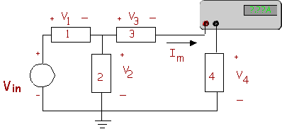
Remember that polarity is important. In the circuit the polarity for the
voltage across element #4 is defined, but the current polarity is not defined.
In the diagram below, we have defined the direction of that current, and given
it an algebraic name, Im.

As with the voltmeter, you need to pay attention
to the polarity, and you also want to remember this.
When you measure current, the
ammeter should not disturb the circuit where you are attempting to measure
the current. In the circuit above, that disturbance is the voltage across
the ammeter. You want that voltage to be as close to zero as it can
possibly be. That means that you need to have the resistance of the
voltmeter as small as possible. Ideally, the resistance of an ammeter would
be zero.
|

