The folded dipole antenna
- Overview, summary, tutorial about the folded dipole antenna, a form of RF
antenna design that is widely used on its own and as the basis for other RF
antenna designs, proving greater bandwidth and higher impedance.
The standard dipole is widely used in its basic form. However
under a number of circumstances a modification of the basic dipole, known as a
folded dipole provides a number of advantages that can be used to advantage.
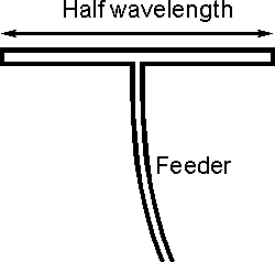
In its basic form a dipole consists of a single wire or
conductor cut in the middle to accommodate the feeder. It is found that the feed
impedance is altered by the proximity of other objects, especially other
parasitic elements that may be used in other forms of RF antenna design. This
can cause problems with matching and because resistance losses in the RF antenna
system can start to become significant.
Additionally many RF antennas have to be able to operate over
large bandwidths and a standard dipole may be unable to fulfil this requirement
adequately.

The basic folded half wave dipole
A variation of the dipole, known as a folded dipole provides
a solution to these problems, offering a wider bandwidth and a considerable
increase in feed impedance. The folded dipole is formed by taking a standard
dipole and then taking a second conductor and joining the two ends. In this way
a complete loop is made as shown. If the conductors in the main dipole and the
second or "fold" conductor are the same diameter, then it is found that there is
a fourfold increase in the feed impedance. In free space, this gives a feed
impedance of around 300 ohms. Additionally the RF antenna has a wider bandwidth.
Impedance increase
In a standard dipole the currents flowing along the
conductors are in phase and as a result there is no cancellation of the fields
and radiation occurs. When the second conductor is added this can be considered
as an extension to the standard dipole with the ends folded back to meet each
other. As a result the currents in the new section flow in the same direction as
those in the original dipole. The currents along both the half-waves are
therefore in phase and the antenna will radiate with the same radiation patterns
etc as a simple half-wave dipole.
The impedance increase can be deduced from the fact that the
power supplied to a folded dipole is evenly shared between the two sections
which make up the antenna. This means that when compared to a standard dipole
the current in each conductor is reduced to a half. As the same power is
applied, the impedance has to be raised by a factor of four to retain balance in
the equation Watts = I^2 x R.
Folded dipole applications
Folded dipoles are sometimes used on their own, but they must
be fed with a high impedance feeder, typically 300 ohms. However they find more
uses when a dipole is incorporated in another RF antenna design with other
elements nearby. This has the effect of reducing the dipole impedance. To ensure
that it can be fed conveniently, a folded dipole may be used to raise the
impedance again to a suitable value.
|