Parabolic reflector antenna
- an overview or tutorial about the parabolic reflector or dish antenna, and
RF antenna design that is widely used for high gain applications such as
satellite transmissions and reception as well as microwave links.
The parabolic reflector or dish antenna has been used far
more widely in recent years with advent of satellite television (TV). However
the dish antenna finds uses in many radio and wireless applications at
frequencies usually above about 1GHz where very high levels of RF antenna gain
are required along with narrow beamwidths. In many professional applications
these parabolic reflectors or dish antennas are used for satellite as well as
for radio astronomy and it is used in many microwave links, often being seen on
radio relay towers and mobile phone antenna masts. In all these applications
very high levels of gain are required to receive the incoming signals that are
often at a very low level. For transmitting this type of RF antenna design is
able to concentrate the available radiated power into a narrow beamwidth,
ensuring all the available power is radiated in the required direction.

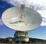
The Goldstone parabolic reflector antenna
Image coutesy NASA
Parabolic reflector basics
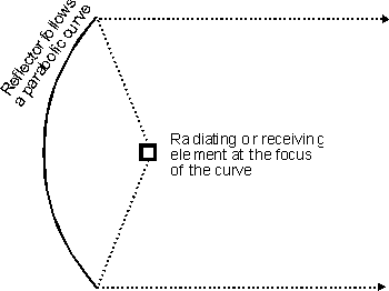
The RF antenna consists of a radiating system that is used to
illuminate a reflector that is curved in the form of a paraboloid. This shape
enables a very accurate beam to be obtained. The antenna exists in two basic
forms. These are termed the focal feed reflector where source of radiation is
placed at the focal point of the parabola and this is used to illuminate the
reflector.
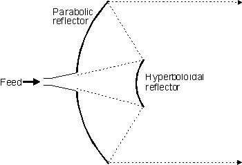
An alternative form of feeding the RF antenna design is known
as a Cassegrain reflector system. Here the radiation is fed through the centre
of the reflector towards a hyperboloidal reflector which reflects the radiation
back onto the paraboloidal reflector. In this way it is possible to control the
radiation more accurately.

Diagram of a focal feed parabolic reflector antenna
The gain is a function of the diameter of the reflecting
surface, the surface accuracy, and the quality of the illumination from the
radiator. Despite these factors it is possible to estimate the gain of the
antenna which can be deduced from the following formula:
G = 10 log10 k (pi D)^2 / lambda^2
where
G is the gain over an isotropic source
k is the efficiency factor which is generally about 50%
D is the diameter of the parabolic reflector in metres
lambda is the wavelength of the signal in metres
From this it can be seen that very large gains can be
achieved if sufficiently large reflectors are used. However when the antenna has
a very large gain, the beamwidth is also very small and the antenna requires
very careful control over its position. In professional systems electrical servo
systems are used to provide very precise positioning.
To provide the optimum illumination of the reflecting
surface, the level of illumination should be greater in the centre than at the
sides. It can be shown that the optimum situation occurs when the centre is
around 10 to 11 dB greater than the illumination at the edge. Lower levels of
edge illumination result in lower levels of side lobes.
The reflecting surface antenna forms a major part of the
whole system. In many respects it is not as critical as may be thought at first.
Often a wire mesh may be used. Provided that the pitch of the mesh is small
compared to a wavelength it will be seen as a continuous surface by the radio
signals. If a mesh is used then the wind resistance will be reduced, and this
provides significant advantages.
Focal feed system
The parabolic reflector or dish antenna consists of a
radiating element which may be a simple dipole or a waveguide horn antenna. This
is placed at the focal point of the parabolic reflecting surface. The energy
from the radiating element is arranged so that it illuminates the reflecting
surface. Once the energy is reflected it leaves the antenna system in a narrow
beam. As a result considerable levels of gain can be achieved.
Achieving this is not always easy because it is dependent
upon the radiator that is used. For lower frequencies a dipole element is often
employed whereas at higher frequencies a circular waveguide may be used. In fact
the circular waveguide provides one of the optimum sources of illumination.
Cassegrain feed system
The Cassegrain feed system, although requiring a second
reflecting surface has the advantage that the overall length of the dish antenna
between the two reflectors is shorter than the length between the radiating
element and the parabolic reflector. This is because there is a reflection in
the focusing of the signal which shortens the physical length. This can be an
advantage in some systems.

Diagram of a focal feed parabolic reflector or dish
antenna with a Cassegrain feed
Summary
For most domestic systems a small reflector combined with a
focal point feed are used, providing the simplest and most economical form of
construction. This is the form that is most widely used for satellite television
applications. These antennas may not always look exactly like the traditional
full dish antenna. For mechanical and production reasons the feed is often
offset from the centre and a portion of the paraboloid used, again offset from
the centre. This provides mechanical advantage. Nevertheless the principles are
exactly the same.
|

