Log periodic antenna
- overview, summary, tutorial about the log periodic antenna or aerial used
for wideband RF antenna applications.
One of the major drawbacks with many RF antennas is that they
have a relatively small bandwidth. This is particularly true of the Yagi beam
antenna. One design named the log periodic is able to provide directivity and
gain while being able to operate over a wide bandwidth.
The log periodic antenna is used in a number of applications
where a wide bandwidth is required along with directivity and a modest level of
gain. It is sometimes used on the HF portion of the spectrum where operation is
required on a number of frequencies to enable communication to be maintained. It
is also used at VHF and UHF for a variety of applications, including some uses
as a television antenna.
Capabilities
The log periodic antenna was originally designed at the
University of Illinois in the USA in 1955.
This type of RF antenna design is directional and is normally
capable of operating over a frequency range of about 2:1. It has many
similarities to the more familiar Yagi because it exhibits forward gain and has
a significant front to back ratio. In addition to this the radiation pattern of
this RF antenna design stays broadly the same over the whole of the operating
band as do parameters like the radiation resistance and the standing wave ratio.
However it offers less gain for its size than does the more conventional Yagi.
Log periodic basics
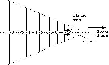
The log periodic antenna can exist in a number of forms. The
most common is the log periodic dipole array (LPDA). It basically consists of a
number of dipole elements. These diminish in size from the back towards the
front. The main beam of this RF antenna coming from the smaller front. The
element at the back of the array where the elements are the largest is a half
wavelength at the lowest frequency of operation. The element spacings also
decrease towards the front of the array where the smallest elements are located.
In operation, as the frequency changes there is a smooth transition along the
array of the elements that form the active region. To ensure that the phasing of
the different elements is correct, the feed phase is reversed from one element
to the next.

A log periodic dipole array
It is possible to explain the operation of a log periodic
array in straightforward terms. The feeder polarity is reversed between
successive elements. Take the condition when this RF antenna is approximately in
the middle of its operating range. When the signal meets the first few elements
it will be found that they are spaced quite close together in terms of the
operating wavelength. This means that the fields from these elements will cancel
one another out as the feeder sense is reversed between the elements. Then as
the signal progresses down the antenna a point is reached where the feeder
reversal and the distance between the elements gives a total phase shift of
about 360 degrees. At this point the effect which is seen is that of two phased
dipoles. The region in which this occurs is called the active region of the RF
antenna. Although the example of only two dipoles is given, in reality the
active region can consist of more elements. The actual number depends upon the
angle [greek letter alpha] and a design constant.
The elements outside the active region receive little direct
power. Despite this it is found that the larger elements are resonant below the
operational frequency and appear inductive. Those in front resonate above the
operational frequency and are capacitive. These are exactly the same criteria
that are found in the Yagi. Accordingly the element immediately behind the
active region acts as a reflector and those in front act as directors. This
means that the direction of maximum radiation is towards the feed point.
Feed arrangements
The log periodic dipole antenna presents a number of
difficulties if it is to be fed properly. The feed impedance is dependent upon a
number of factors. However it is possible to control this by altering the
spacing, and hence the impedance for the feeder that connects each of the dipole
elements together. Despite this the impedance varies with frequency, but this
can be overcome to a large extent by making the longer elements out of a larger
diameter rod. Even so the final feed impedance does not normally match to 50
ohms on its own. It is normal for a further form of impedance matching to be
required. This may be in the form of a stub or even a transformer. The actual
method employed will depend to a large degree on the application of the antenna
and its frequency range.,/p>
Overview
The log periodic antenna is a particularly useful design when
modest levels of gain are required, combined with wideband operation. A typical
example of this type of RF antenna design will provide between 4 and 6 dB gain
over a bandwidth of 2:1 while retaining an SWR level of better than 1.3:1. With
this level of performance it is ideal for many applications, although a log
periodic antenna will be much larger than a Yagi that will produce equivalent
gain. However the Yagi is unable to operate over such a wide bandwidth.
|

