The J or J Pole Antenna
- the J pole antenna is a vertical RF antenna that does not require radials
The J antenna or J pole antenna has found favour in many
applications. The J antenna has a number of advantages over the standard
vertical RF antennas such as the quarter wavelength vertical antenna and the
five eights wavelength antenna. Unlike the other vertical RF antennas just
mentioned, the J pole antenna does not require radials for its operation. In
applications where radials may appear unsightly or where they may not be
suitable for other reasons, the J pole antenna provides a useful alternative.
Additionally its length means that the J pole antenna also provides some gain
over a normal quarter wavelength vertical. These two attributes make the j pole
antenna the ideal type for many applications. As a result the J Pole antenna is
finding many applications, many of which are at VHF and above. Here it forms a
compact self contained RF antenna that can fit in many locations and can give a
high level of performance without a large visual impact.
Although the fact that the J antenna does not have any
radials may make it appear that it will not work, it is a well established RF
antenna design. It is a form of RF antenna design known as a Zepp or Zeppelin
antenna that found favour in the 1930s as an HF antenna. This antenna gained its
name from the fact that it was used on the Zeppelin airships. The Rf antenna
design consists of a half wave radiating element which is end fed using a
quarter wave stub of open wire or 300 Ohm balanced feeder used to match the
impedance to the normal 50 Ohm coaxial feeder.

The development of the J or J Pole antenna
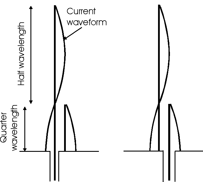
The diagram shows the development of the J pole antenna and
its operation. This shows the RF antenna radiating element which is a half
wavelength. Being end fed this presents a high impedance to the feeder and this
is matched using a half wave matching stub. In the first form of the antenna,
the radiating element is fed from the source, with the other leg of the stub
providing a passive balance. It can also be seen that it is possible to feed the
antenna using the other arm of the stub.

The development of the J antenna or J Pole antenna
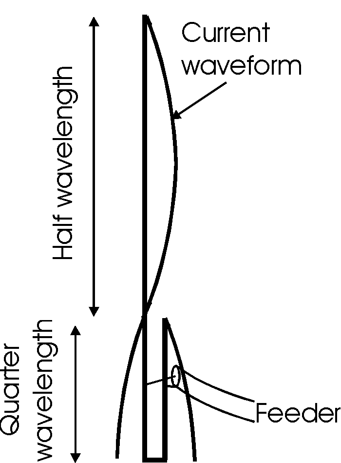
The final implementation of the J pole antenna uses the stub
to provide a good match to 50 Ohm cable. The feed point is moved up or down the
stub to provide the best match, and adjustment can be made once the antenna is
in position if required. In this way any spurious changes resulting from the
position, etc can be removed.
Construction
The J pole antenna is quite easy to construct and gives good
results. The main disadvantage is that it can be a little more difficult to
adjust than some other forms. The reason for this is that impedance matching has
to be accomplished by altering the trimming length of the stub.
The length of the half wave radiating stub for the j pole
antenna can be determined using the same formula as used in calculating the
length of a half wave dipole. The physical length of the balanced feeder will
depend on the velocity factor of the feeder in use. For open wire feeder the
velocity factor is nearly unity and the length will be very close to that of the
free space quarter wavelength. If 300 twin feeder is used then the length
required will be shorter because its velocity factor is about 0.85.
Summary
The J pole antenna is a very useful form of RF antenna
design. It can be used in many applications and can be particualrly useful where
an RF antenna desihgn is needed without radials. Also providing some gain, it
provides an efficient radiator for the available space. Against this it can be
detuned by nearby objects.
|

