Quarter wave vertical antenna
- overview or summary about the basics of the quarter wave vertical and
ground plane antennas that ares widely used for medium wave broadcasting, mobile
radio communications applications and many more.
Vertical antennas are widely used at all frequencies from MF
up to VHF and beyond. They exist in a variety of forms including the quarter
wave vertical and ground plane antennas. They possess many advantages and are
widely used for medium wave broadcasting as well as for mobile applications in
areas including private mobile radio.
The reason for this widespread use is the omni-directional
radiation pattern that they give in the horizontal plane. This means that the
antennas do not have to be re-orientated to keep the signals constant as the car
moves it position.
Single element vertical antennas posses an omni-directional
radiation pattern (in the horizontal plane). This means that the antennas do not
have to be re-orientated when used in mobile applications as the vehicle moves.
This is obviously an essential requirement.
A further advantage is that much of the radiation is at right
angles to the antenna element, and as a result it travels close to the earth's
surface where the receiving stations are located. Radiation directed upwards is
wasted in many instances as VHF transmissions are normally not reflected by the
ionosphere.,
For medium wave broadcast stations a particular advantage is
that the radiation is vertically polarised. It is found that the vertically
polarised transmissions propagate further via the ground wave that these
transmissions use.
Basic element
Like the name suggests the antenna consists of a quarter
wavelength vertical element. The antenna is what is termed "un-balanced" having
one connection to the vertical element and using an earth connection or
simulated earth connection to provide an image for the other connection.
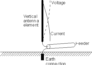
The voltage and current waveforms show that at the end the
voltage rises to a maximum whereas the current falls to a minimum. Then at the
base of the antenna at the feed point, the voltage is at a minimum and the
current is at its maximum. This gives the antenna a low feed impedance.
Typically this is around 20 ohms.

A quarter wave vertical RF antenna design
The ground is obviously an important part of the RF antenna.
Many MF and HF installations use a ground connection for this. These ground
systems need to be very effective fort he antenna to perform satisfactorily.
They must obviously have a very low resistance, and often utilise large "mats"
of radials extending out from the base of the antenna to ensure excellent RF
performance.
For VHF and UHF installations, height is obviously important
and antennas need to be raised to ensure they are above the nearby obstructions.
Also for mobile installations it is clearly not possible to use a true earth
connection. In these cases a simulated earth is used. For mobile applications
this consists of the body of the vehicle. The antenna mounting will normally
enable a suitable connection to be made to the vehicle body, sometimes using a
capacitive connection. However it is necessary to ensure that the vehicle body
is metal, and not plastic in the vicinity of the antenna mounting.
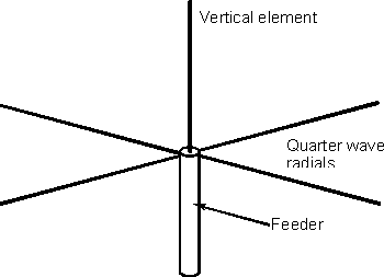
For fixed stations a set of radials simulating a ground plane
is used. In theory the ground plane should extend out to infinity, but in
practice a number of radials a quarter wavelength long is used. Typically for
many VHF applications four radials is sufficient.

A radial system used with a quarter wave vertical
If the radials are bent downwards from the horizontal then
the feed impedance will be raised. A 50 ohm match is achieved when the angle
between the ground plane rods and the horizontal is 42 degrees. Another solution
is to include an impedance matching element in the antenna. Normally this is in
the form of a tapped coil that can be conveniently housed in the base of the
antenna.
Folded element
In view of the low impedance presented to the feeder by the
RF antenna, methods must be found of presenting a good match and some have
already been outlined. Another is to use a folded element. In the same way that
a folded dipole increases the feed impedance of the antenna, so a folded
vertical element can be used. If the diameter of both sections is the same, then
an increase by a ratio of 4:1 is achieved. This would bring the impedance to 80
ohms and will provide an acceptable match to 75 ohm feeder. By using a smaller
diameter grounded element the feed impedance can be reduced so that a good match
to 50 ohm coax can be achieved.
Summary
The quarter wave vertical antenna is widely used in view of
its simplicity and convenience. To improve on its performance other types of
vertical are available. It is also possilbe to use further verticals and feed
them with different phases to provide gain to the overall antenna system.
|

