Resistor attenuator circuits
- for use in radio frequency circuits including receivers and
transmitters, etc
Attenuator circuits are used in a variety of radio frequency circuit design
applications. The attenuators reduce the level of the signal and this can be
used to ensure that the correct radio signal level enters another circuit block
such as mixer or amplifier so that it is not overloaded. As such attenuators are
widely used by radio frequency circuit designers. While it is possible to buy
ready made attenuators, it is also easy to make attenuators for many
applications. Here a simple resistor network can be used to make attenuators
that provide levels of attenuation up to figures of 60 dB and at frequency of 1
GHz and more, provided that care is taken with the construction and the choice
of components.
One important feature that is required for radio frequency applications is
that the characteristic impedance should be maintained. In other words the
impedance looking into and out of the attenuator should be matched to the
characteristic impedance of the system.
T and Pi networks
There are two basic formats that can be used for resistive attenuators. They are
the T and pi networks. Often there is little to choose between them and the
choice is often down to the preference of the designer.
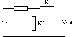
As the name suggests the "T"section attenuator is in the shape of the letter
T with two resistors in the signal line and one in the centre to ground.

T section attenuator
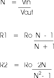
The two resistor values can be calculated very easily knowing the ratio of
the input and output voltages, Vin and Vout respectively and the characteristic
impedance Ro.

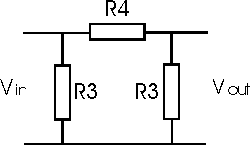
The pi section attenuator is in the form of the Greek letter pi and has one
in line resistor and a resistor to ground at the input and the output.

Pi section attenuator
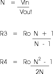
Similarly the values for the pi section attenuator can be calculated

Practical aspects
It is generally good practice not to attempt to achieve any more than a maximum
of 20 dB attenuation in any one attenuator section. Even this is possibly a
little high. It is therefore common practice to cascade several sections. When
this is done the adjoining resistors can be combined. In the case of the T
section attenuator this simply means the two series resistors can be added
together. For the pi section attenuators there are parallel resistors.
When making large value attenuators, great care must be taken to prevent the
signal leaking past the attenuator and reaching the output. This can result from
capacitive or inductive coupling and poor earth arrangements. To overcome these
problems good earth connection and careful layout, keeping the output and input
away from one another are required. It may also be necessary to place a screen
between the different sections.
Using these attenuators a surprisingly good frequency response can be
obtained. Non-inductive resistors are required to ensure the best performance,
and using good printed circuit board techniques and surface mount resistors, a
good performance at frequencies in excess of 1 GHz are easy to achieve.
Table of resistor values for 50 ohm attenuators
Resistor designations refer to diagrams above
|
Loss in dB |
R1 |
R2 |
R3 |
R4 |
|
1 |
2.9 |
433 |
870 |
5.8 |
|
2 |
5.7 |
215 |
436 |
11.6 |
|
3 |
8.5 |
142 |
292 |
17.6 |
|
4 |
11.3 |
105 |
221 |
23.8 |
|
5 |
14.0 |
82.2 |
179 |
30.4 |
|
6 |
16.6 |
66.9 |
151 |
37.3 |
|
7 |
19.1 |
55.8 |
131 |
44.8 |
|
8 |
21.5 |
47.3 |
116 |
52.8 |
|
9 |
23.8 |
40.6 |
105 |
61.6 |
|
10 |
26.0 |
35.1 |
96.2 |
71.2 |
|
11 |
28.0 |
30.6 |
89.2 |
81.7 |
|
12 |
29.9 |
26.8 |
83.5 |
93.2 |
|
13 |
31.7 |
23.6 |
78.8 |
106 |
|
14 |
33.4 |
20.8 |
74.9 |
120 |
|
15 |
34.9 |
18.4 |
71.6 |
136 |
|
16 |
36.3 |
16.3 |
68.8 |
154 |
|
17 |
37.6 |
14.4 |
66.5 |
173 |
|
18 |
38.8 |
12.8 |
64.4 |
195 |
|
19 |
39.9 |
11.4 |
62.6 |
220 |
|
20 |
40.9 |
10.1 |
61.1 |
248 |
|

