High impedance inverting op amp circuit
a high input impedance version of the inverting operational
amplifier or op-amp circuit
The standard inverting amplifier configuration is widely used
with operational amplifier integrated circuits. It has many advantages: being
simple to construct; it offers the possibility of summation or mixing (in the
audio sense) of several signals; and of course it inverts the signal which can
be important in some instances.
However the circuit does have some drawbacks which can be
important on some occasions. The main drawback is its input impedance. To show
how this can be important it is necessary to look at the circuit and take some
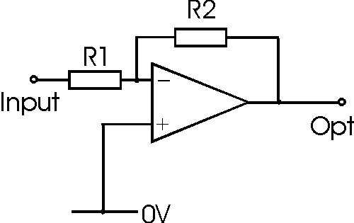
examples. The basic circuit for the inverting operational amplifier circuit is
shown below. It consists of a resistor from the input terminal to the inverting
input of the circuit, and another resistor connected from the output to the
inverting input of the op-amp. The non inverting input is connected to ground.

Basic inverting operational amplifier circuit
The gain for the amplifier can be calculated from the
formula:
Av = R2 / R1
If a high gain of, for example 100, is required this means
that the ratio of R2 : R1 is 100. It is good practice to keep the resistors in
op amp circuits within reasonable bounds. In view of this the maximum value for
R2 should be 1 M Ohm. This means that the input resistor and hence the input
resistance to the amplifier circuit as a whole is 10 k Ohm. In some instances
this may not be sufficiently high.
To overcome this problem it is possible to modify the
circuit, and add a couple of extra resistors. The feedback resistor R2 serves to
limit the amount of feedback. The higher it is the less feedback, and hence the
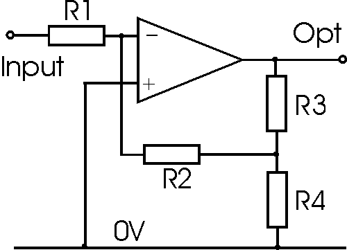
higher the gain. By adding a couple of additional resistors across the output to
act as a potential divider and taking the resistor R2 from the centre point, the
level of feedback can be reduced. The circuit for this configurations is shown
below:

High input impedance inverting operational amplifier
circuit
The gain for this amplifier can be calculated from the
formula:
Av = R2 (R3 + R4) / (R1 x R4 )
Again the input resistance is equal to R1, but this can be
made higher for the same gain.
Reminder
It is worth mentioning at this point that for high levels of gain, the gain
bandwidth product of the basic op amp itself may become a problem. With levels
of gain of 100, the bandwidth of some operational amplifier ICs may only be
around 3 kHz. Check the data sheet for the given chip being used before settling
on the level of gain.
|