Operational amplifier comparator
- a simple comparator circuit using a single op amp
Comparator circuits find a number of applications in
electronics. As the name implies they are used to compare two voltages. When one
is higher than the other the comparator circuit output is in one state, and when
the input conditions are reversed, then the comparator output switches.
These circuits find many uses as detectors. They are often
used to sense voltages. For example they could have a reference voltage on one
input, and a voltage that is being detected on another. While the detected
voltage is above the reference the output of the comparator will be in one
state. If the detected voltage falls below the reference then it will change the
state of the comparator, and this could be used to flag the condition. This is
but one example of many for which comparators can be used.
In operation the op amp goes into positive or negative
saturation dependent upon the input voltages. As the gain of the operational
amplifier will generally exceed 100 000 the output will run into saturation when
the inputs are only fractions of a millivolt apart.
Although op amps are widely used as comparator, special
comparator chips are often used. These integrated circuits offer very fast
switching times, well above those offered by most op-amps that are intended for
more linear applications. Typical slew rates are in the region of several
thousand volts per microsecond, although more often figures of propagation delay
are quoted.
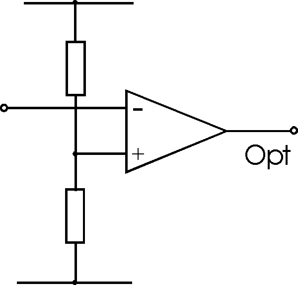
A typical comparator circuit will have one of the inputs held
at a given voltage. This may often be a potential divider from a supply or
reference source. The other input is taken to the point to be sensed.

Circuit for a basic operational amplifier comparator
There are a number of points to remember when using
comparator circuits. As there is no feedback the two inputs to the circuit will
be at different voltages. Accordingly it is necessary to ensure that the maximum
differential input is not exceeded. Again as a result of the lack of feedback
the load will change. Particularly as the circuit changes there will be a small
increase in the input current. For most circuits this will not be a problem, but
if the source impedance is high it may lead to a few unusual responses.
The main problem with this circuit is that new the changeover
point, even small amounts of noise will cause the output to switch back and
forth. Thus near the changeover point there may be several transitions at the
output and this may give rise to problems elsewhere in the overall circuit. The
solution to this is to use a Schmitt Trigger as described on another page.
|