Operational amplifier low pass filter
-a summary of operational amplifier or op-amp active low pass filter
circuitry
Operational amplifiers lend themselves to being used for
active filter circuits, including a low pass filter circuit. Using a few
components they are able to provide high levels of performance.
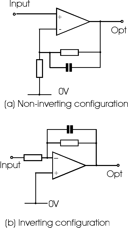
The simplest circuit low pass filter circuit using an
operational amplifier simply places a capacitor across the feedback resistor.
This has the effect as the frequency rises of increasing the level of feedback
as the reactive impedance of the capacitor falls. The break point for this
simple type of filter can be calculated very easily by working out the frequency
at which the reactance of the capacitor equals the resistance of the resistor.
This can be achieved using the formula:
Xc = 2 pi f C
where:
Xc is the capacitive reactance in ohms
pi is the greek letter and equal to 3.142
f is the frequency in Hertz
C is the capacitance in Farads

Operational amplifier circuits with high frequency
roll off
While these operational amplifier circuits are useful to
provide a reduction in gain at high frequencies, they only provide an ultimate
rate of roll off of 6 dB per octave, i.e. the output voltage halves for every
doubling in frequency. This type of filter is known as a one pole filter. Often
a much grater rate of rejection is required, and to achieve this it is possible
to incorporate a higher performance filter into the feedback circuitry.
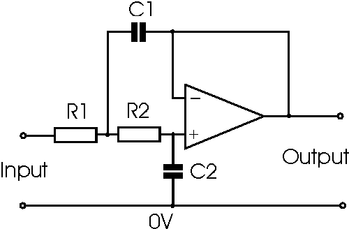
Two pole low pass filter
Although it is possible to design a wide variety of filters with different
levels of gain and different roll off patterns using operational amplifiers, the
filter described on this page will give a good sure-fire solution. It offers
unity gain and a Butterworth response (the flattest response in band, but not
the fastest to achieve ultimate roll off out of band).

Operational amplifier two pole low pass filter
Simple sure fire design with Butterworth response and unity gain
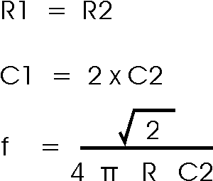
The calculations for the circuit values are very
straightforward for the Butterworth response and unity gain scenario. Critical
damping is required for the circuit and the ratio of the resistor and capacitor
values determines this.

When choosing the values, ensure that the resistor values
fall in the region between 10 k ohms and 100 k ohms. This is advisable because
the output impedance of the circuit rises with increasing frequency and values
outside this region may affect he performance.
|