Operational amplifier basics
Overview of the operational amplifier or op-amp as a circuit
building block
Operational amplifiers are one of the workhorses of the
analogue electronics scene. They are virtually the ideal amplifier, providing a
combination of a very high gain, a very high input impedance and a very low
output impedance. The input to the operational amplifier has differential
inputs, and these enable the operational amplifier circuit to be used in an
enormous variety of circuits.
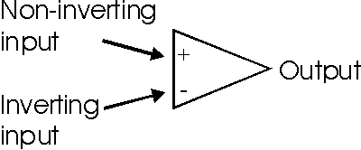
The circuit symbol for an operational amplifier consists
simply of a triangle as shown below. The two inputs are designated by "+" and
"-" symbols, and the output of the operational amplifier is at the opposite end
of the triangle. Inputs from the "+" input appear at the output in the same
phase, whereas signals present at the "-" input appear at the output inverted or
180 degrees out of phase. This gives rise to the names for the inputs. The "+"
input is known as the non-inverting input, while the "-" input is the inverting
input of the operational amplifier.

Operational amplifier circuit symbol
Often the power supply rails for the operational amplifier
are not shown in circuit diagrams and there is no connection for a ground line.
The power rails for the operational amplifier are assumed to be connected. The
power for the operational amplifier is generally supplied as a positive rail and
also a negative rail. Often voltages of +15V and -15 V are used, although this
will vary according to the application and the actual chip used.
The gain of the operational amplifier is very high. Figures
for the levels of gain provided by an operational amplifier on its own are very
high. Typically they may be upwards of 10 000.
While levels of gain may be too high for use on their own,
the application of feedback around the operational amplifier enables the circuit
to be used in a wide variety of applications, from very flat amplifiers, to
filters, oscillators, switches, and much more.
Open loop gain
The gain of an operational amplifier is exceedingly high. Normally feedback is
applied around the op-amp so that the gain of the overall circuit is defined and
kept to a figure which is more usable. However the very high level of gain of
the op-amp enables considerable levels of feedback to be applied to enable the
required performance to be achieved.
When measured the open loop gain of an operational amplifier
falls very rapidly with increasing frequency. Typically an op-amp may have an
open loop gain of around 10^5, but this usually starts to fall very quickly. For
the famous 741 operational amplifier, it starts to fall at a frequency of only
10 Hz.
Slew rate
With very high gains the operational amplifiers have what is termed compensation
capacitance to prevent oscillation. This capacitance combined with the limited
drive currents mean that the output of the amplifier is only able to change at a
limited rate, even when a large or rapid change occurs at the input. This
maximum speed is known as the slew rate. A typical general purpose device may
have a slew rate of 10 V / microsecond. This means that when a large step change
is placed on the input, the device would be able to provide an output 10 volt
change in one microsecond.
The figures for slew rate change are dependent upon the type
of operational amplifier being used. Low power op-amps may only have a slew rate
of a volt per microsecond, whereas there are fast operational amplifiers capable
to providing slew rates of 1000 V / microsecond.
The slew rate can introduce distortion onto a signal by
limiting the frequency of a large signal that can be accommodated. It is
possible to find the maximum frequency or voltage that can be accommodated. A
sine wave with a frequency of f Hertz and amplitude V volts requires an
operational amplifier with a slew rate of 2 x pi x V x V volts per second.
Offset null
One of the minor problems with an operational amplifier is that they have a
small offset. Normally this is small, but it is quoted in the datasheets for the
particular operational amplifier in question. It is possible to null this using
an external potentiometer connected to the three offset null pins.
|

