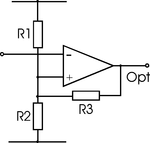
Operational amplifier Schmitt trigger
- a simple circuit using an op amp to produce a
Schmitt trigger to remove multiple transitions on slow input signals
Although the simple comparator circuit using either an
ordinary operational amplifier ( op-amp ) or a special comparator chip is often
adequate, if the input waveform is slow or has noise on it, then there is the
possibility that the output will switch back and forth several times during the
switch over phase as only small levels of noise on the input will cause the
output to change. This may not be a problem in some circumstances, but if the
output from the operational amplifier comparator is being fed into fast logic
circuitry, then it can often give rise to problems.
The problem can be solved very easily by adding some positive
feedback to the operational amplifier or comparator circuit. This is provided by
the addition of R3 in the circuit below and the circuit is known as a Schmitt
trigger.

Operational amplifier Schmitt trigger circuit
The effect of the new resistor (R3) is to give the circuit
different switching thresholds dependent upon the output state of the comparator
or operational amplifier. When the output of the comparator is high, this
voltage is fed back to the non-inverting input of the operational amplifier of
comparator. As a result the switching threshold becomes higher. When the output
is switched in the opposite sense, the switching threshold is lowered. This
gives the circuit what is termed hysteresis.
The fact that the positive feedback applied within the
circuit ensures that there is effectively a higher gain and hence the switching
is faster. This is particularly useful when the input waveform may be slow.
However a speed up capacitor can be applied within the Schmitt trigger circuit
to increase the switching speed still further. By placing a capacitor across the
positive feedback resistor R3, the gain can be increased during the changeover,
making the switching even faster. This capacitor , known as a speed up capacitor
may be anywhere between 10 and 100 pF dependent upon the circuit.
It is quite easy to calculate the resistors needed in the
Schmitt trigger circuit. The centre voltage about which the circuit should
switch is determined by the potential divider chain consisting of R1 and R2.
This should be chosen first. Then the feedback resistor R3 can be calculated.
This will provide a level of hysteresis that is equal to the output swing of the
circuit reduced by the potential divide formed as a result of R3 and the
parallel combination of R1 and R2.
|