Diode single balanced mixer
-a circuit of a diode single balanced mixer and its typical
applications for radio frequency, RF circuits
Mixers are widely used for radio frequency of RF
applications. The mixers used in this arena multiply the two signals entering
the circuit together. (note - audio mixers add signals together). The multiplier
type mixers used in radio frequency applications are formed using non-linear
devices. As a result the two signals entering the circuit are multiplied
together - the output at any given time is proportional to the product of the
levels of the two signals entering the circuit at that instant. This gives rise
to signals at frequencies equal to the sum and the difference of the frequencies
of the two signals entering the circuit.
One of the simpler mixer circuits is based around two diodes.
This type of diode known as a single balanced diode mixer circuit provides
rejection of the input signals at the output as a result of the fact that the
two inputs are balanced.
The circuit is only singly balanced and as a result it does
not give isolation between the two input ports. This means that the signal from
the local oscillator may leak onto the signal input line and this may give rise
to intermodulation distortion. However for many applications this circuit
operates quite satisfactorily. Where this may be a problem then a double
balanced mixer should be used.

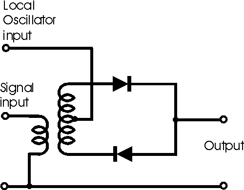
The circuit of a diode single balanced mixer
The circuit has a typical conversion loss, i.e. the
difference between the signal input and the output of around 8dB, although this
depends upon the components used and the construction. The diodes should be as
nearly matched as possible, and the transformer should be closely balanced for
optimum rejection of the input signals at the output.
Where the input signals are widely spaced in frequency, it is
possible to utilise a variation of the basic single balanced diode mixer to good
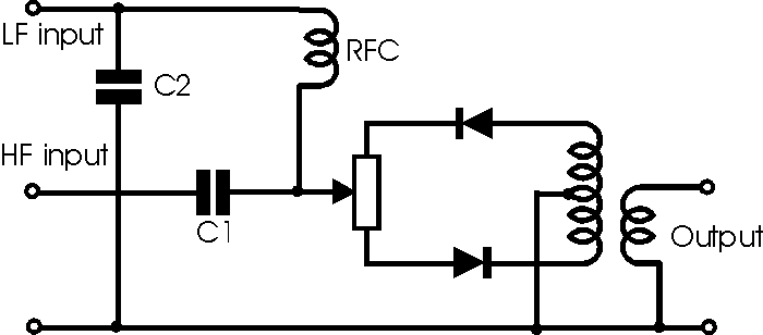
effect. The circuit which is shown below may be used in a variety of
applications, for example where an audio signal needs to be modulated onto a
radio frequency, RF, carrier. In the circuit the two signals are combined using
C1 as a high pass filter, and the combination of RFC and C2 as a low pass
filter. In this way the leakage between the two input ports is minimised. A
further refinement is that a balance control is incorporated into the balanced
mixer circuit. This is used to ensure optimum balance. For example when used for
modulating an RF carrier, it can be used to minimise the level of the carrier at
the output, thereby ensuring only the two sidebands are produced.

The circuit of a diode single balanced mixer with a
balance control
Although this form of the single balanced diode mixer circuit
does require a few more components, the performance is improved as the variable
resistor enables much better balance to be achieved, and additionally there is
some form of isolation between the two inputs.
|