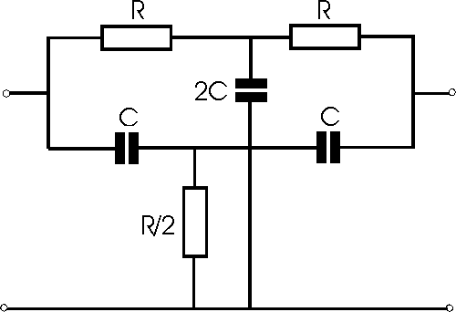
Twin T notch filter
- design and circuit considerations for a resistor capacitor (RC)
twin T notch filter
The twin T circuit is very useful as a notch filter. Here the
twin T provides a large degree of rejection at a particular frequency. This
notch filter can be useful in rejecting unwanted signals that are on a
particular frequency. One example may be to filter out unwanted mains hum at 50
or 60 Hz that may be entering a circuit.
The response provided by the filter consists of a low level
of attenuation away from the notch frequency. As signals move closer to the
notch frequency, the level of attenuation rises, giving the typical notch filter
response. In theory, at the notch frequency the level of attenuation provided by
the twin T notch filter is infinite.

RC - Resistor Capacitor Twin T Notch Filter
The circuit for the twin T notch filter is shown above and
can be seen to consist of three resistors and three capacitors. It operates by
phase shifting the signals in the different legs and adding them at the output.
At the notch frequency, the signals passing through each leg are 180 degrees out
of phase and cancel out. In theory this provides a complete null of the signal.
However in practice close tolerance components are required to achieve a good
null.
In common with other RC circuits, the RC twin T notch filter
circuit has what may be termed as a soft cut-off. The response of the notch
circuit falls away slowly and affects a wide band of frequencies either side of
the cut-off frequency. However very close to the cut-off frequency the response
falls away very quickly, assuming that close tolerance components have been
used.
Calculation of the value for the circuit is very
straightforward.
fc = 1 / (2 pi R C)
Where:
fc = cut off frequency in Hertz
pi = 3.142
R and C are the values of the resistors and capacitors as in the circuit
|