Quartz crystal filter
- summary, overview or tutorial about the basics of the quartz crystal
filter describing its operation, use, design and specification.
Quartz crystal filters provide an effective means of
realising filter solutions for many high performance radio frequency filter
applications. The high Q values that quartz crystals possess can be utilised in
bandpass filters for use in areas such as radio receivers. These quartz crystal
filters are far superior to those that could be manufactured using LC
components. Although they are more costly than LC filters, the performance of a
quartz crystal filter is still superior and in terms of cost they actually
provide excellent value for money.
Today, quartz crystal filters can be designed with pass bands
ranging from frequencies in the kilohertz region up to many Megahertz - with the
latest technology this can rise to 100 MHz and more. However for the best
performance and lowest costs the passband of the filter is generally kept to
below about 30 MHz or so.
Quartz crystal overview
Quartz crystals use the piezo electric effect to convert the
incoming electrical impulses into mechanical vibrations. These vibrations are
affected by the mechanical resonances of the crystal, and as the piezo electric
effect operates in both directions, the mechanical resonances affect the
electrical stimuli, being reflected back into the electrical circuit.
The levels of Q that can be achieved using quartz crystals
range into figures well over 10 000. Values of 100 000 are widely used in
filters and values can sometimes reach 500 000. By utilising this level of
performance, quartz crystal filters can achieve very high levels of performance.
This can be reflected in the crystal filters very narrow filter bandwidths and
sharp cut-off curves.
Quartz crystal cuts
When manufacturing the quartz crystal blanks used to make the
electronic components used in filters, the angle at which these blanks are cut
from the unprepared crystal, have a major bearing on the properties. A form of
cut known as the AT cut is used for most radio applications. This provides the
optimum set of parameters for most radio applications. The size of the crystal
blank using this cut is such that it is sufficiently robust to withstand the
manufacturing process without a high level of failures and rejects, and to
withstand the vibration that is likely to be expected in use. Additionally the
level of spurious responses is low. A further advantage is that the temperature
stability is high. The final angle of the cut can be adjusted to ensure that the
temperature characteristic is optimum for the particular application for which
it is intended. Even a difference of 2 minutes of arc can be detected, although
the normal manufacturing spread is around 3 minutes of arc.
In addition to this the cut of the quartz crystal governs the
way in which it vibrates. As there are several modes in which a crystal can
vibrate it is necessary to choose a cut in which unwanted modes are not easy to
excite. If they are present then they will be seen as spurious responses in the
crystal filter.
Quartz crystal filter parameters
There are two main areas of interest for a filter, the pass
band where it accepts signals and allows them through, and the stop band where
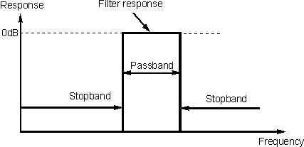
it rejects them. In an ideal world a filter would have a response something like
that shown below. Here it can be seen that there is an immediate transition
between the pass band and the stop band. Also in the pass band the filter does
not introduce any loss and in the stop band no signal is allowed through.

The response of an ideal filter
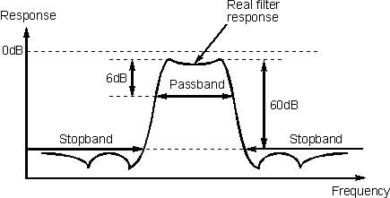
In reality it is not possible to realise a filter with these
characteristics and a typical response more like that shown in Figure 3. It is
fairly obvious from the diagram that there are a number of differences. The
first is that there is some loss in the pass band. Secondly the response does
not fall away infinitely fast. Thirdly the stop band attenuation is not
infinite, even though it is very large. Finally it will be noticed that there is
some in band ripple.

Typical response of a real filter
In most filters the attenuation in the pass band is normally
relatively small. For a typical crystal filter figures of 2 - 3 dB are fairly
typical. However it is found that very narrow band filters like those used for
Morse reception may be higher than this. Fortunately it is quite easy to
counteract this loss simply by adding a little extra amplification in the
intermediate frequency stages and this factor is not quoted as part of the
receiver specification.
It can be seen that the filter response does not fall away
infinitely fast, and it is necessary to define the points between which the pass
band lies. For receivers the pass band is taken to be the bandwidth between the
points where the response has fallen by 6 dB, i.e. where it is 6 dB down or -6
dB.
A stop band is also defined. For most receiver filters this
is taken to start at the point where the response has fallen by 60 dB, although
the specification for the filter should be checked this as some filters may not
be as good. Sometimes a filter may have the stop band defined for a 50 dB
attenuation rather than 60 dB.
Shape factor
It can be seen that it is very important for the filter to
achieve its final level of rejection as quickly as possible once outside the
pass band. In other words the response should fall as quickly as possible. To
put a measure on this, a figure known as the shape factor is used. This is
simply a ratio of the bandwidths of the pass band and the stop band. Thus a
filter with a pass band of 3 kHz at -6dB and a figure of 6 kHz at -60 dB for the
stop band would have a shape factor of 2:1. For this figure to have real meaning
the two attenuation figures should also be quoted. As a result the full shape
factor specification should be 2:1 at 6/60 dB.
Quartz crystal filter design parameters
When a quartz crystal filter is designed factors such as the
input and output impedance as well as bandwidth, crystal Q and many other
factors need to be taken into account.
Some of the chief factors are obviously the bandwidth, shape
fact, and ultimate cutoff. Although it is very much a simplification, these
factors are dependent upon the number of poles (equivalent to the number of
crystals), their Q value, and their individual frequencies.
Further factors such as the maximum bandwidth that can be
achieved is controlled by the filter impedance and also the spurious responses
that are present in the individual quartz crystal elements. The location of the
important responses for quartz crystal filters can be controlled by the size of
the plates deposited onto the crystals. By making them smaller the responses
also become less critical. The down side of this is that the impedance of the
overall quartz crystal filter rises. This means that the quartz crystal filter
will need impedance transformers at the input and the output. This obviously
needs to be avoided if at all possible, but for wide band filters it is often
the only option.
Summary
Quartz crystal filters are widely used in many applications,
and particularly for radio applications. Here these quartz crystal filter
provide an exceptional level of performance, and bearing this in mind their cost
is very reasonable.
|

