Phase noise and frequency synthesizers
One of the main problems with frequency synthesisers and frequency synthesis
using phase locked loops is the fact that some designs generate high levels of
phase noise. However it is possible to design some very good low phase noise
synthesizers. The problem is often that receivers and transceivers are designed
for low production costs, and this naturally means that some short cuts are
needed.
What is phase noise?
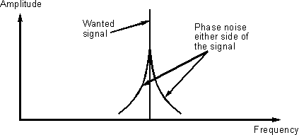
Phase noise is present on all signals to some degree and it is caused by small
phase (and hence frequency) perturbations or jitter on the signal. It manifests
itself as noise spreading out either side from the main carrier

Phase noise on a signal
Some signal sources are better than others. Crystal oscillators are very good
and have very low levels of phase noise. Free running variable frequency
oscillators normally perform well. Unfortunately synthesizers, and especially
those based around phase locked loops, do not always fare so well unless they
are well designed. If significant levels of phase noise are present on a
synthesizer used as a local oscillator in a receiver, it can adversely affect
the performance of the radio in terms of reciprocal mixing.
Some oscillators have phase noise levels that are quoted in their
specifications. Any high quality signal generator will have the level of phase
noise specified, as do many high performance crystal oscillators used as
standards. Their performance is generally specified in dBc/Hz and at a given
offset from the carrier. The term dBc simply refers to the level of noise
relative to the carrier, i.e. -10 dBc means that the level is 10 lower than the
carrier.
The bandwidth in which the noise is measured also has to be specified. The
reason for this is that noise spreads over the frequency spectrum. Obviously the
wider bandwidth that is used, the greater the level of noise that will pass
through the filter and be measured. To prove this, just try selecting a
different bandwidth on a receiver and check what happens to the noise level. It
will rise for a wider bandwidth and fall when a narrow bandwidth is used.
Technically the most convenient bandwidth to use a 1 Hz bandwidth and so this is
used. When measuring this a wider bandwidth is usually used because it is
difficult to obtain 1 Hz bandwidth filters and a correction is made
mathematically.
Finally the level of noise varies as different offsets from the carrier are
taken. Accordingly this must be included in a specification. A very good
oscillator might have a specification of -100 dBc/Hz at 10 kHz offset.
It has already been mentioned that the level of phase noise changes as the
offset from the carrier changes and for "simple" signal sources like crystal
oscillators or variable frequency oscillators the phase noise reduces as the
frequency from the main carrier is increased. For frequency synthesizers the
picture is a little more complicated as we shall see.
Phase noise in synthesizers
Each of the components in a frequency synthesizer produces noise that will
contribute to the overall noise that appears at the output. The actual way in
which the noise from any one element in the loop contributes to the output will
depend upon where it is produced. Noise generated by the VCO will affect the
output in a different way to that generated in the phase detector for example.
To see how this happens take the example of noise generated by the voltage
controlled oscillator. This will pass through the divider chain and appear at
the output of the phase detector. It will then have to pass through the loop
filter. This will only allow through those components of the noise that are
below the loop cut-off frequency. These will appear on the error voltage and
have the effect of cancelling out the noise on the voltage controlled
oscillator. As this effect will only take place within the loop bandwidth, it
will reduce the level of noise within the loop bandwidth and have no effect on
noise outside the loop bandwidth.
Noise generated by the phase detector is affected in a different way. Again
only the components of the noise below the loop bandwidth will pass through the
low pass filter. This means that there will be no components outside the loop
bandwidth appearing on the tune voltage at the control terminal of the voltage
controlled oscillator, and there will be no effect on the oscillator. Those
components inside the loop bandwidth will appear at the oscillator control
terminal. These will affect the oscillator and appear as phase noise on the
output of the voltage controlled oscillator.
Matters are made worse by the fact that the division ratio has the effect of
multiplying the noise level. This arises because the synthesizer effectively has
the effect of multiplying the frequency of the reference. Consequently the noise
level is also multiplied by a factor of 20 log N, where N is the division ratio.
Noise generated by the reference undergoes exactly the same treatments as
that generated by the phase detector. It too is multiplied by the division ratio
of the loop in the same way that the phase detector noise is. This means that
even though the reference oscillator may have a very good phase noise
performance this can be degraded significantly, especially if division ratios
are high.
Dividers normally do not produce a significant noise contribution. Any noise
they produce may be combined with that of the phase detector.
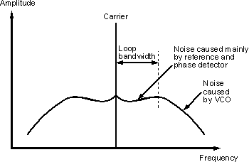
The combined noise of the loop at the output generally looks like that shown
in Figure 2. Here it can be seen that the noise within the loop bandwidth arises
from the phase detector and the reference. Outside the loop bandwidth it arises
primarily from the voltage controlled oscillator. From this it can be seen that
optimisation of the noise profile is heavily dependent upon the choice of the
loop bandwidth. It is also necessary to keep the division ratio in any loop down
to reasonable levels. For example a 150 MHz synthesizer with a 12.5 kHz step
size will require a division ratio of 12000. In turn this will degrade the phase
detector and reference phase noise figures by 81 dB inside the loop bandwidth -
a significant degradation by anyone's standards! Provided that division ratios
are not too high then a wide loop bandwidth can help keep the voltage controlled
oscillator noise levels down as well.

Noise profile of a typical synthesizer
Effects of phase noise
Phase noise can have a number of effects. For SSB transmitters like those used
for HF communications for ship to shore, amateur radio and other applications
the main effect is that splatter appears either side of the main signal. This
results from the phase noise either side of the signal will rising and falling
in line with the amplitude variations of the main signal. For digital
transmissions using frequency or phase modulation, the noise can introduce
errors causing the bit error rate (BER) to rise.
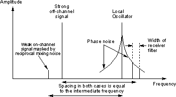
For receivers the main problem is an effect known as reciprocal mixing. To
look at how this occurs take the case of a superhet receiver tuned to a strong
signal. The signal will pass through the radio frequency stages, and then in the
mixer it will be mixed with the local oscillator to produce a new signal at the
right frequency to pass through the IF filters. When the local oscillator is
tuned away by ten kilohertz, for example the signal will no longer be able to
pass through the IF filters. However it will still be possible for the phase
noise on the local oscillator to mix with the strong incoming signal to produce
a signal that will fall inside the receiver pass-band as shown in Figure 3. This
could be sufficiently strong to mask out a weak station.

The way in which phase noise on a signal results in
reciprocal mixing
Specifications
A number of different methods are used to define the level of reciprocal mixing.
Generally they involve the response of the receiver to a large off channel
signal. To perform a reciprocal mixing measurement is rarely easy. The signal
generator must always be much better than the receiver, otherwise the
performance of the signal generator will be measured! To overcome this many
people use an old valve generator because their performance is often very good
in this respect.
A measurement can be made by noting the level of audio with a BFO on from a
small signal. The signal is then tuned off channel by a given amount, normally
about 20 kHz and then increased until the audio level rises to the same level as
a result of the phase noise from the receiver. As the noise level is dependent
upon the bandwidth of the receiver this has to be specified as well. Generally a
bandwidth useable for SSB is used i.e. 2.7 kHz.
For example a good HF communications receiver might have a figure of 95 dB at
a 20 kHz offset using a 2.7. kHz bandwidth. This figure will improve as the
frequency offset from the main channel is increased. At 100 kHz one might expect
to see a figure in excess of 105 dB or possibly more.
Another way of measuring the phase noise response is to inject a large signal
into the receiver and monitor the level needed to give a 3 dB increase in
background noise level.
|

