Millman's Theorem
San Luis Obispo, Calif. In the last article in this series, we applied
Norton equivalents to a simple three resistor circuit. Let's try generalizing
the analysis to come up with Millman's Theorem.
Millman's Theorem is named after Jacob Millman. Mr. Millman was born in
Russia in 1911 received a Ph.D. from MIT in 1935. He went on to write eight
textbooks on electronics between 1941 and 1987 and was a professor of electrical
engineering at Columbia University.

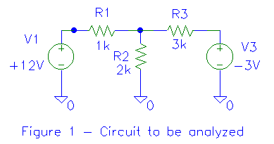
As you may recall from the last article in the series, we took the circuit of
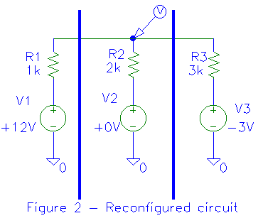
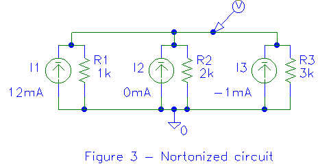
figure 1, reconfigured it as shown in figure 2, then converted the voltage
sources with series resistances to current sources with parallel resistances
(Norton equivalents). Note that the ground at the bottom of R2 has
been replaced with a zero volt voltage source (V2) to
ground. Recall that a "piece of wire" can be replaced with a zero
volt voltage source. Adding this voltage source makes each branch of the circuit
identical (a voltage source with a series resistance). Let's generalize the
analysis by keeping the V's and R's, instead of substituting values.
Each voltage source with a series resistance is converted to a current source
with a parallel resistance. The current is the "short circuit current" of the
circuit which we are "Nortonizing". We find that I1=V1/R1
, I2=V2/R2, I3=V3/R3.
As the circuit is expanded, it's fairly obvious that IN=VN/RN.
Further, as we determined last time, the Norton resistance (that resistance we
will place across the current source) is the same as the Thevenin resistance
(that resistance in series with the voltage source). We determine the Thevenin
resistance by shorting out the voltage sources and opening any current sources
in the circuit we are trying to simplify, then measure the resulting resistance.
For example, in the left portion of figure 2, we short out V1,
setting it to zero volts. We then measure the resistance from the top of R1
to ground, getting (surprise!) R1 ohms. Figure 3 shows the circuit of
figure 2 reconfigured to use Norton equivalents for each section.

This is pretty much where we left off last time. We added the parallel
current sources to get the total current and applied this to the combined
parallel resistance to find the voltage at the junction of the resistances.
Let's generalize it! The total current is:
I1 + I2 + I3(V1/R1)
+ (V2/R2) + (V3/R3)
Further, the equivalent parallel resistance is:
1/((1/R1)+(1/R2)+(1/R3))
Finally, the voltage at the resistor junctions is determined by multiplying
the total current by the parallel resistance (Ohm's Law):
V=IRV=((V1/R1)+(V2/R2)+(V3/R3))
* (1/((1/R1)+(1/R2)+(1/R3))
V=((V1/R1)+(V2/R2)+(V3/R3))/((1/R1)+(1/R2)+(1/R3))
The last equation is Millman's theorem. It might be more easily remembered by
considering its components. If we replace the R in V=IR with 1/G (where G is
conductance measured in Siemens) and replace V/R with I, the equation becomes:
V=(I1+I2+I3)/(G1+G2+G3)

Generalizing for any number of sources and resistances,
V=(I1+I2+I3+...IN)/(G1+G2+G3+...GN)
It would be interesting to try to derive Millman's theorem using other
circuit analysis technqiues. Let's see if we can derive it using superposition
next month!
|