|
The degrees of freedom (DOF) of a rigid body is
defined as the number of independent movements it has. Figure 4-1
shows a rigid body in a plane. To determine the DOF of this body we
must consider how many distinct ways the bar can be moved. In a two
dimensional plane such as this computer screen, there are 3 DOF. The
bar can be translated along the x axis, translated
along the y axis, and rotated about its centroid.

Figure 4-1 Degrees of freedom of a rigid body in a plane
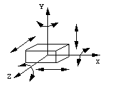
An unrestrained rigid body in space has six degrees of freedom: three
translating motions along the x, y and z axes and three
rotary motions around the x, y and z axes respectively.
Two or more rigid bodies in space are collectively called a rigid body
system. We can hinder the motion of these independent rigid bodies with
kinematic constraints. Kinematic constraints are constraints
between rigid bodies that result in the decrease of the degrees of freedom of
rigid body system.
The term
kinematic pairs actually refers to kinematic constraints between
rigid bodies. The kinematic pairs are divided into
lower pairs and
higher pairs, depending on how the two bodies are in contact.
There are two kinds of lower pairs in planar mechanisms:
revolute pairs and
prismatic pairs.
A rigid body in a plane has only three independent motions -- two
translational and one rotary -- so introducing either a revolute pair or a
prismatic pair between two rigid bodies removes two degrees of freedom.

Figure 4-3 A planar revolute pair (R-pair)

Figure 4-4 A planar prismatic pair (P-pair)
There are six kinds of lower pairs under the category of
spatial mechanisms. The types are:
spherical pair,
plane pair,
cylindrical pair,
revolute pair,
prismatic pair, and
screw pair.

Figure 4-5 A spherical pair (S-pair)
A spherical pair keeps two spherical centers together. Two
rigid bodies connected by this constraint will be able to rotate
relatively around x, y and z axes, but there
will be no relative translation along any of these axes. Therefore,
a spherical pair removes three degrees of freedom in spatial
mechanism. DOF = 3.

Figure 4-6 A planar pair (E-pair)
A plane pair keeps the surfaces of two rigid bodies
together. To visualize this, imagine a book lying on a table where
is can move in any direction except off the table. Two rigid bodies
connected by this kind of pair will have two independent
translational motions in the plane, and a rotary motion around the
axis that is perpendicular to the plane. Therefore, a plane pair
removes three degrees of freedom in spatial mechanism. In our
example, the book would not be able to raise off the table or to
rotate into the table. DOF = 3.

Figure 4-7 A cylindrical pair (C-pair)
A cylindrical pair keeps two axes of two rigid bodies
aligned. Two rigid bodies that are part of this kind of system will
have an independent translational motion along the axis and a
relative rotary motion around the axis. Therefore, a cylindrical
pair removes four degrees of freedom from spatial mechanism. DOF
= 2.

Figure 4-8 A revolute pair (R-pair)
A revolute pair keeps the axes of two rigid bodies
together. Two rigid bodies constrained by a revolute pair have an
independent rotary motion around their common axis. Therefore, a
revolute pair removes five degrees of freedom in spatial mechanism.
DOF = 1.

Figure 4-9 A prismatic pair (P-pair)
A prismatic pair keeps two axes of two rigid bodies align
and allow no relative rotation. Two rigid bodies constrained by this
kind of constraint will be able to have an independent translational
motion along the axis. Therefore, a prismatic pair removes five
degrees of freedom in spatial mechanism. DOF = 1.

Figure 4-10 A screw pair (H-pair)
The screw pair keeps two axes of two rigid bodies aligned
and allows a relative screw motion. Two rigid bodies constrained by
a screw pair a motion which is a composition of a translational
motion along the axis and a corresponding rotary motion around the
axis. Therefore, a screw pair removes five degrees of freedom in
spatial mechanism.
Rigid bodies and kinematic constraints are the basic components
of mechanisms. A constrained rigid body system can be a
kinematic chain, a
mechanism, a structure, or none of these. The influence of
kinematic constraints in the motion of rigid bodies has two
intrinsic aspects, which are the geometrical and physical aspects.
In other words, we can analyze the motion of the constrained rigid
bodies from their geometrical relationships or using
Newton's Second Law.
A mechanism is a constrained rigid body system in which one of
the bodies is the
frame. The degrees of freedom are important when considering a
constrained rigid body system that is a mechanism. It is less
crucial when the system is a structure or when it does not have
definite motion.
Calculating the degrees of freedom of a rigid body system is
straight forward. Any unconstrained rigid body has six degrees of
freedom in space and three degrees of freedom in a plane. Adding
kinematic constraints between rigid bodies will correspondingly
decrease the degrees of freedom of the rigid body system. We will
discuss more on this topic for planar mechanisms in the next
section.
The definition of the degrees of freedom of a
mechanism is the number of independent relative motions among the
rigid bodies. For example,
Figure 4-11 shows several cases of a rigid body constrained by
different kinds of pairs.

Figure 4-11 Rigid bodies constrained by different kinds of
planar pairs
In Figure 4-11a, a rigid body is constrained by a
revolute pair which allows only rotational movement around an
axis. It has one degree of freedom, turning around point A. The two
lost degrees of freedom are translational movements along the x
and y axes. The only way the rigid body can move is to rotate
about the fixed point A.
In Figure 4-11b, a rigid body is constrained by a
prismatic pair which allows only translational motion. In two
dimensions, it has one degree of freedom, translating along the x
axis. In this example, the body has lost the ability to rotate about
any axis, and it cannot move along the y axis.
In Figure 4-11c, a rigid body is constrained by a
higher pair. It has two degrees of freedom: translating along
the curved surface and turning about the instantaneous contact
point.
In general, a rigid body in a plane has three degrees of freedom.
Kinematic pairs are constraints on rigid bodies that reduce the
degrees of freedom of a mechanism. Figure 4-11 shows the three kinds
of pairs in
planar mechanisms. These
pairs reduce the number of the degrees of freedom. If we create
a
lower pair (Figure 4-11a,b), the degrees of freedom are reduced
to 2. Similarly, if we create a
higher pair (Figure 4-11c), the degrees of freedom are reduced
to 1.
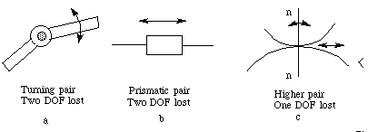
Figure 4-12 Kinematic Pairs in Planar Mechanisms
Therefore, we can write the following equation:
 (4-1)
(4-1)Where
- F = total degrees of freedom in the mechanism
- n = number of
links (including the
frame)
- l = number of
lower pairs (one degree of freedom)
- h = number of
higher pairs (two degrees of freedom)
This equation is also known as Gruebler's equation.
Look at the transom above the door in Figure 4-13a. The opening
and closing mechanism is shown in Figure 4-13b. Let's calculate its
degree of freedom.
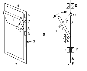
Figure 4-13 Transom mechanism
n = 4 (link 1,3,3 and frame 4), l = 4 (at A, B, C, D), h = 0
 (4-2)
(4-2)Note: D and E function as a same prismatic pair, so
they only count as one lower pair.
Example 2
Calculate the degrees of freedom of the mechanisms shown in
Figure 4-14b. Figure 4-14a is an application of the mechanism.
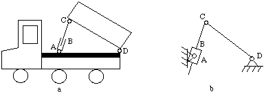
n = 4, l = 4 (at A, B, C, D), h = 0
 (4-3)
(4-3)
Calculate the degrees of freedom of the
mechanisms shown in Figure 4-15.

Figure 4-15 Degrees of freedom calculation
For the mechanism in Figure 4-15a
n = 6, l = 7, h = 0
 (4-4)
(4-4)For the mechanism in Figure 4-15b
n = 4, l = 3, h = 2
 (4-5)
(4-5)
Note: The rotation of the roller does not influence the
relationship of the input and output motion of the mechanism. Hence,
the freedom of the roller will not be considered; It is called a
passive or redundant degree of freedom.
Imagine that the roller is welded to link 2 when counting the
degrees of freedom for the mechanism.
The number of
degrees of freedom of a mechanism is also called the mobility
of the device. The mobility is the number of input
parameters (usually pair variables) that must be independently
controlled to bring the device into a particular position. The
Kutzbach criterion, which is similar to
Gruebler's equation, calculates the mobility.
In order to control a mechanism, the number of independent input
motions must equal the number of degrees of freedom of the
mechanism. For example, the transom in
Figure 4-13a has a single degree of freedom, so it needs one
independent input motion to open or close the window. That is, you
just push or pull rod 3 to operate the window.
To see another example, the mechanism in
Figure 4-15a also has 1 degree of freedom. If an independent
input is applied to link 1 (e.g., a motor is mounted on joint
A to drive link 1), the mechanism will have the a prescribed motion.
Finite transformation is used to describe the motion of a point
on rigid body and the motion of the rigid body itself.
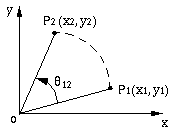
Figure 4-16 Point on a planar rigid body rotated through an
angle
Suppose that a point P on a rigid body goes through a
rotation describing a circular path from P1 to
P2 around the origin of a coordinate system. We can
describe this motion with a rotation operator R12:
 (4-6)
(4-6)
where
 (4-7)
(4-7)
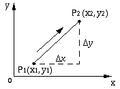
Suppose that a point P on a rigid
body goes through a translation describing a straight path from P1
to P2 with a change of coordinates of ( x, x,
 y).
We can describe this motion with a translation operator T12: y).
We can describe this motion with a translation operator T12:
 (4-8)
(4-8)where
 (4-9)
(4-9)

Suppose that a point P on a rigid
body goes through a rotation describing a circular path from P1
to P2' around the origin of a coordinate system,
then a translation describing a straight path from P2'
to P2. We can represent these two steps by
 (4-10)
and
 (4-11)
We can
concatenate these motions to get
 (4-12)
where D12
is the planar general displacement operator :
 (4-13)
We have discussed various transformations to describe the
displacements of a point on rigid body. Can these operators be
applied to the displacements of a system of points such as a rigid
body?
We used a 3 x 1 homogeneous column matrix to describe a vector
representing a single point. A beneficial feature of the planar 3 x
3 translational, rotational, and general displacement matrix
operators is that they can easily be programmed on a computer to
manipulate a 3 x n matrix of n column vectors representing n points
of a rigid body. Since the distance of each particle of a rigid body
from every other point of the rigid body is constant, the vectors
locating each point of a rigid body must undergo the same
transformation when the rigid body moves and the proper axis, angle,
and/or translation is specified to represent its motion. (Sandor
& Erdman 84). For example, the general planar transformation for
the three points A, B, C on a rigid body can be represented
by
 (4-14)
We can describe a spatial rotation operator for the rotational
transformation of a point about an unit axis u passing
through the origin of the coordinate system. Suppose the rotational
angle of the point about u is
 ,
the rotation operator will be expressed by ,
the rotation operator will be expressed by
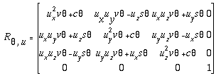 (4-15)
where
- ux, uy, uz are the
othographical projection of the unit axis u on x,
y, and z axes, respectively.
- s
 = sin
= sin
- c
 = cos
= cos
- v
 = 1 - cos
Suppose that a point P on a rigid body goes through a
translation describing a straight path from P1 to
P2 with a change of coordinates of ( x, x,
 y, y,
 z),
we can describe this motion with a translation operator T: z),
we can describe this motion with a translation operator T:
 (4-16)
Suppose a point P on a rigid body rotates with an angular
displacement about an unit axis u passing through the origin
of the coordinate system at first, and then followed by a
translation Du along u. This composition of
this rotational transformation and this translational transformation
is a screw motion. Its corresponding matrix operator, the
screw operator, is a concatenation of the translation
operator in
Equation 4-7 and the rotation operator in
Equation 4-9.
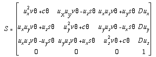 (4-17)
For a system of rigid bodies, we can establish a local Cartesian
coordinate system for each rigid body. Transformation matrices are
used to describe the relative motion between rigid bodies.
For example, two rigid bodies in a space each have local
coordinate systems x1y1z1 and x2y2z2.
Let point P be attached to body 2 at location (x2,
y2, z2) in body 2's local coordinate system.
To find the location of P with respect to body 1's local
coordinate system, we know that that the point x2y2z2
can be obtained from x1y1z1 by
combining translation Lx1 along the x axis
and rotation
 z
about z axis. We can derive the transformation matrix as follows: z
about z axis. We can derive the transformation matrix as follows:
 (4-18)
If rigid body 1 is fixed as a
frame, a global coordinate system can be created on this body.
Therefore, the above transformation can be used to map the local
coordinates of a point into the global coordinates.
The transformation matrix above is a specific example for two
unconstrained rigid bodies. The transformation matrix depends on the
relative position of the two rigid bodies. If we connect two rigid
bodies with a
kinematic constraint, their degrees of freedom will be
decreased. In other words, their relative motion will be specified
in some extent.
Suppose we constrain the two rigid bodies above with a
revolute pair as shown in Figure 4-19. We can still write the
transformation matrix in the same form as
Equation 4-18.
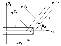
Figure 4-19 Relative position of points on constrained bodies
The difference is that the Lx1 is a constant
now, because the revolute pair fixes the origin of coordinate system
x2y2z2 with respect to coordinate
system x1y1z1. However, the
rotation
 z
is still a variable. Therefore, kinematic constraints specify the
transformation matrix to some extent. z
is still a variable. Therefore, kinematic constraints specify the
transformation matrix to some extent.
Denavit-Hartenberg notation
(Denavit & Hartenberg 55) is widely used in the transformation
of coordinate systems of
linkages and robot mechanisms. It can be used to represent the
transformation matrix between links as shown in the Figure 4-20.
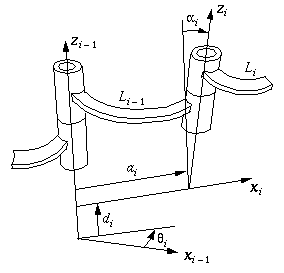
In this figure,
The transformation matrix will be T(i-1)i
 (4-19)
The above transformation matrix can be denoted
as T(ai,
 i, i,
 i,
di) for convenience. i,
di) for convenience.
A linkage is composed of several constrained rigid bodies. Like a
mechanism, a linkage should have a frame. The matrix method can be
used to derive the kinematic equations of the linkage. If all the
links form a closed loop, the concatenation of all of the
transformation matrices will be an identity matrix. If the mechanism
has n links, we will have:
T12T23...T(n-1)n
= I
|

