| Introduction to Mechanisms |
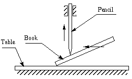
Figure 6-1 Simple Cam experiment
Take a pencil and a book to do an experiment as shown above. Make the book an
inclined plane and use the pencil as a slider (use your hand as a guide). When
you move the book smoothly upward, what happens to the pencil? It will be pushed
up along the guide. By this method, you have transformed one motion into another
motion by a very simple device. This is the basic idea of a cam. By rotating the
cams in the figure below, the bars will have either translational or oscillatory
motion.
The transformation of one of the simple motions, such as rotation, into any
other motions is often conveniently accomplished by means of a cam mechanism
A cam mechanism usually consists of two moving elements, the cam and the
follower, mounted on a fixed frame. Cam devices are versatile, and almost any
arbitrarily-specified motion can be obtained. In some instances, they offer the
simplest and most compact way to transform motions.
A cam may be defined as a machine element having a curved
outline or a curved groove, which, by its oscillation or rotation motion, gives
a predetermined specified motion to another element called the follower
. The cam has a very important function in the operation of many classes of
machines, especially those of the automatic type, such as printing presses, shoe
machinery, textile machinery, gear-cutting machines, and screw machines. In any
class of machinery in which automatic control and accurate timing are paramount,
the cam is an indispensable part of mechanism. The possible applications of cams
are unlimited, and their shapes occur in great variety. Some of the most common
forms will be considered in this chapter.
We can classify cam mechanisms by the modes of input/output motion, the
configuration and arrangement of the follower, and the shape of the cam. We can
also classify cams by the different types of motion events of the follower and
by means of a great variety of the motion characteristics of the cam profile.
(Chen 82)
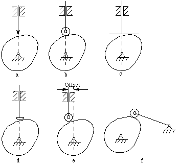
Figure 6-2 Classification of cam mechanisms
- Rotating cam-translating follower. (Figure
6-2a,b,c,d,e)
- Rotating follower (Figure
6-2f):
The follower arm swings or oscillates in a circular arc with respect to the
follower pivot.
- Translating cam-translating follower (Figure
6-3).
- Stationary cam-rotating follower:
The follower system revolves with respect to the center line of the vertical
shaft.
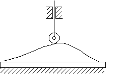
Figure 6-3 Translating cam - translating follower
- Knife-edge follower (Figure
6-2a)
- Roller follower (Figure
6-2b,e,f)
- Flat-faced follower (Figure
6-2c)
- Oblique flat-faced follower
- Spherical-faced follower (Figure
6-2d)
- In-line follower:
The center line of the follower passes through the center line of the
camshaft.
- Offset follower:
The center line of the follower does not pass through the center line of the
cam shaft. The amount of offset is the distance between these two
center lines. The offset causes a reduction of the side thrust present in
the roller follower.
- Plate cam or disk cam:
The follower moves in a plane perpendicular to the axis of rotation of the
camshaft. A translating or a swing arm follower must be constrained to
maintain contact with the cam profile.
- Grooved cam or closed cam (Figure
6-4):
This is a plate cam with the follower riding in a groove in the face of the
cam.
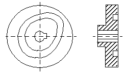
Figure 6-4 Grooved cam
- Cylindrical cam or barrel cam (Figure
6-5a):
The roller follower operates in a groove cut on the periphery of a cylinder.
The follower may translate or oscillate. If the cylindrical surface is
replaced by a conical one, a conical cam results.
- End cam (Figure
6-5b):
This cam has a rotating portion of a cylinder. The follower translates or
oscillates, whereas the cam usually rotates. The end cam is rarely used
because of the cost and the difficulty in cutting its contour.
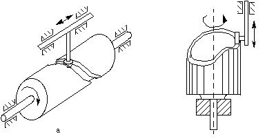
Figure 6-5 Cylindrical cam and end cam
- Gravity constraint:
The weight of the follower system is sufficient to maintain contact.
- Spring constraint:
The spring must be properly designed to maintain contact.
- Positive mechanical constraint:
A groove maintains positive action. (Figure
6-4 and
Figure 6-5a) For the cam in Figure 6-6, the follower has two rollers,
separated by a fixed distance, which act as the constraint; the mating cam
in such an arrangement is often called a constant-diameter cam.
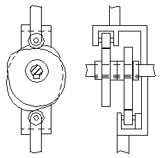
Figure 6-6 Constant diameter cam
A mechanical constraint cam also be introduced by employing a dual or
conjugate cam in arrangement similar to what shown in Figure 6-7. Each cam
has its own roller, but the rollers are mounted on the same reciprocating or
oscillating follower.
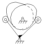
Figure 6-7 Dual cam
Rotating Cam, Translating Follower
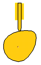
Figure 6-8 SimDesign translating cam
Load the SimDesign file simdesign/cam.translating.sim. If you turn
the cam, the follower will move. The weight of the follower keeps them in
contact. This is called a gravity constraint cam.
Rotating Cam/Rotating Follower
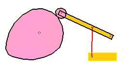
The SimDesign file is simdesign/cam.oscillating.sim.
Notice that a roller is used at the end of the follower. In addition, a spring
is used to maintain the contact of the cam and the roller.
If you try to calculate the
degrees of freedom (DOF) of the mechanism, you must imagine that the roller
is welded onto the follower because turning the roller does not influence the
motion of the follower.
Figure 6-10 illustrates some cam nomenclature:
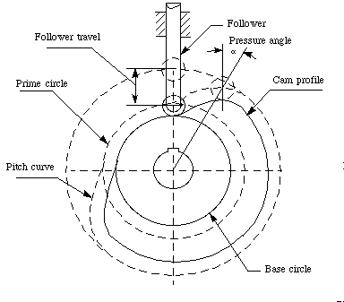
Figure 6-10 Cam nomenclature
- Trace point: A theoretical point on the follower, corresponding
to the point of a fictitious knife-edge follower. It is used to
generate the pitch curve. In the case of a roller follower,
the trace point is at the center of the roller.
- Pitch curve: The path generated by the trace point at the
follower is rotated about a stationary cam.
- Working curve: The working surface of a cam
in contact with the follower. For the knife-edge follower of the
plate cam, the pitch curve and the working curves coincide. In
a close or grooved cam there is an inner profile and an
outer working curve.
- Pitch circle: A circle from the cam center through the pitch
point. The pitch circle radius is used to calculate a cam of minimum size
for a given pressure angle.
- Prime circle (reference circle): The smallest circle from
the cam center through the pitch curve.
- Base circle: The smallest circle from the cam center through the
cam profile curve.
- Stroke or throw:The greatest distance or angle through
which the follower moves or rotates.
- Follower displacement: The position of the follower from a
specific zero or rest position (usually its the position when the f
ollower contacts with the base circle of the cam) in relation to time
or the rotary angle of the cam.
- Pressure angle: The angle at any point between the normal to the
pitch curve and the instantaneous direction of the follower motion. This
angle is important in cam design because it represents the steepness of the
cam profile.
When the cam turns through one motion cycle, the follower executes a series
of events consisting of rises, dwells and returns. Rise is the motion of
the follower away from the cam center, dwell is the motion during which
the follower is at rest; and return is the motion of the follower toward
the cam center.
There are many follower motions that can be used for the rises and the
returns. In this chapter, we describe a number of basic curves.
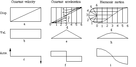
Figure 6-11 Motion events
Notation
-
 :
The rotary angle of the cam, measured from the beginning of the motion
event; :
The rotary angle of the cam, measured from the beginning of the motion
event;
-
 :
The range of the rotary angle corresponding to the motion event; :
The range of the rotary angle corresponding to the motion event;
- h : The stoke of the motion event of the follower;
- S : Displacement of the follower;
- V : Velocity of the follower;
- A : Acceleration of the follower.
If the motion of the follower were a straight line,
Figure 6-11a,b,c, it would have equal displacements in equal units of time,
i.e., uniform velocity from the beginning to the end of the stroke, as
shown in b. The acceleration, except at the end of the stroke would be zero, as
shown in c. The diagrams show abrupt changes of velocity, which result in large
forces at the beginning and the end of the stroke. These forces are undesirable,
especially when the cam rotates at high velocity. The constant velocity
motion is therefore only of theoretical interest.

(6-1)
Constant acceleration motion is shown in
Figure 6-11d, e, f. As indicated in e, the velocity increases at a uniform
rate during the first half of the motion and decreases at a uniform rate during
the second half of the motion. The acceleration is constant and positive
throughout the first half of the motion, as shown in f, and is constant and
negative throughout the second half. This type of motion gives the follower the
smallest value of maximum acceleration along the path of motion. In high-speed
machinery this is particularly important because of the forces that are required
to produce the accelerations.
When
 , ,
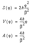
(6-2)
When
 , ,
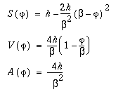
(6-3)
A cam mechanism with the basic curve like g in
Figure 6-7g will impart simple harmonic motion to the follower. The
velocity diagram at h indicates smooth action. The acceleration, as shown at i,
is maximum at the initial position, zero at the mid-position, and negative
maximum at the final position.
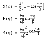
(6-4)
The translational or rotational displacement of the follower is a function of
the rotary angle of the cam. A designer can define the function according to the
specific requirements in the design. The motion requirements, listed below, are
commonly used in cam profile design.
Figure 6-12 is a skeleton diagram of a disk cam with a knife-edge translating
follower. We assume that the cam mechanism will be used to realize the
displacement relationship between the rotation of the
cam and the translation of the
follower.
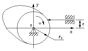
Figure 6-12 A Skeleton Diagram of disk cam with knife-edge translation
Below is a list of the essential parameters for the evaluation of these types
of cam mechanisms. However, these parameters are adequate only to define a
knife-edge follower and a
translating follower cam mechanism.
Parameters:
- ro: The radius of the
base circle;
- e: The
offset of the follower from the rotary center of the cam. Notice: it
could be negative.
- s: The displacement of the follower which is a function of the
rotary angle of the cam --
 . .
- IW: A parameter whose absolute value is 1. It represents the
turning direction of the cam. When the cam turns clockwise: IW=+1,
otherwise: IW=-1.
The method termed
inversion is commonly used in cam profile design. For example, in a disk cam
with
translating follower mechanism, the follower translates when the cam turns.
This means that the relative motion between them is a combination of a relative
turning motion and a relative translating motion. Without changing this feature
of their relative motion, imagine that the cam remains fixed. Now the follower
performs both the relative turning and translating motions. We have inverted the
mechanism.
Furthermore, imagine that the
knife-edge
of the follower moves along the fixed cam profile in the inverted mechanism. In
other words, the
knife edge of the follower draws the profile of the cam. Thus, the problem
of designing the cam profile becomes a problem of calculating the trace of the
knife edge of the follower whose motion is the combination of the relative
turning and the relative translating.
Design equations:
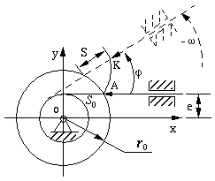
Figure 6-13 Profile design of translating cam follower
In Figure 6-13, only part of the cam profile AK is displayed. Assume
the cam turns clockwise. At the beginning of motion, the knife edge of the
follower contacts the point of intersection A of the
base circle and the cam profile. The coordinates of A are (So, e),
and So can be calculated from equation

Suppose the displacement of the follower is S when the angular
displacement of the cam is
 .
At this moment, the coordinates of the knife edge of the follower should be (So
+ S, e). .
At this moment, the coordinates of the knife edge of the follower should be (So
+ S, e).
To get the corresponding position of the knife edge of the follower in the
inverted mechanism, turn the follower around the center of the cam in the
reverse direction through an angle of
 .
The knife edge will be inverted to point K, which corresponds to the
point on the cam profile in the inverted mechanism. Therefore, the coordinates
of point K can be calculated with the following equation: .
The knife edge will be inverted to point K, which corresponds to the
point on the cam profile in the inverted mechanism. Therefore, the coordinates
of point K can be calculated with the following equation:

(6-5)
Note:
- The
offset e is negative if the follower is located below the x
axis.
- When the rotational direction of the cam is clockwise: IW = +1,
otherwise: IW = -1.
Suppose the cam mechanism will be used to make the knife edge oscillate. We
need to compute the coordinates of the cam profile that results in the required
motion of the follower.
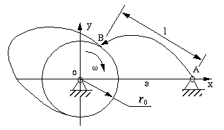
Figure 6-14 Disk cam with knife-edge oscillating follower
The essential parameters in this kind of cam mechanisms are given below.
- ro: The radius of the
base circle;
- a: The distance between the pivot of the cam and the pivot of the
follower.
- l: The length of the follower which is a distance from its pivot
to its knife edge.
-
 :
The angular displacement of the follower which is a function of the rotary
angle of the cam -- :
The angular displacement of the follower which is a function of the rotary
angle of the cam --
 . .
- IP: A parameter whose absolute value is 1. It represents the
location of the follower. When the follower is located above the x
axis: IP=+1, otherwise: IP=-1.
- IW: A parameter whose absolute value is 1. It represents the
turning direction of the cam. When the cam turns clockwise: IW=+1,
otherwise: IW=-1.
Cam profile design principle
The fundamental principle in designing the cam profiles is still
inversion, similar to that that for designing other cam mechanisms, (e.g.,
the
translating follower cam mechanism). Normally, the follower oscillates when
the cam turns. This means that the relative motion between them is a combination
of a relative turning motion and a relative oscillating motion. Without changing
this feature of their relative motion, let the cam remain fixed and the follower
performs both the relative turning motion and oscillating motion. By imagining
in this way, we have actually inverted the mechanism.
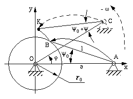
Figure 6-15 Cam profile design for a rotating follower
In Figure 6-15, only part of the cam profile BK is shown. We assume
that the cam turns clockwise.
At the beginning of motion, the
knife edge of the follower contacts the point of intersection (B) of
the base circle and the cam profile. The initial angle between the follower (AB)
and the line of two pivots (AO) is
 0.
It can be calculated from the triangle OAB. 0.
It can be calculated from the triangle OAB.
When the angular displacement of the cam is
 ,
the oscillating displacement of the follower is ,
the oscillating displacement of the follower is
 which measures from its own initial position. At this moment, the angle between
the follower and the line passes through two pivots should be
 + + 0. 0.
The coordinates of the
knife edgeat this moment will be

(6-6)
To get the corresponding knife-edge of the follower in the inverted
mechanism, simply turn the follower around the center of the cam in the reverse
direction of the cam rotation through an angle of
 .
The knife edge will be inverted to point K which corresponds to the point
on the cam profile in the inverted mechanism. Therefore, the coordinates of
point K can be calculated with the following equation: .
The knife edge will be inverted to point K which corresponds to the point
on the cam profile in the inverted mechanism. Therefore, the coordinates of
point K can be calculated with the following equation:

(6-7)
Note:
- When the initial position of the follower is above the x axis,
IP = +1, otherwise: IP = -1.
- When the rotary direction of the cam is clockwise: IW = +1,
otherwise: IW = -1.
Additional parameters:
- r: the radius of the roller.
- IM: a parameter whose absolute value is 1, indicating which
envelope curve will be adopted.
- RM: inner or outer envelope curve. When it is an inner envelope
curve: RM=+1, otherwise: RM=-1.
Design principle:
The basic principle of designing a cam profile with the
inversion method is still used. However, the curve is not directly generated
by inversion. This procedure has two steps:
- Imagine the center of the roller as a knife edge. This concept is
important in cam profile design and is called the
trace point) of follower. Calculate the
pitch curve aa, that is, the trace of the pitch point in the
inverted mechanism.
- The cam profile bb is a product of the enveloping motion of a
series of rollers.
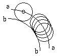
The problem of calculating the coordinates of the cam
profile is the problem of calculating the tangent points of a sequence of
rollers in the inverted mechanism. At the moment shown Figure 6-17, the tangent
point is P on the cam profile.
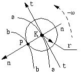
The calculation of the coordinates of the point P
has two steps:
- Calculate the slope of the tangent tt of point
K on
pitch curve, aa.
- Calculate the slope of the normal nn of the curve aa at
point K.
Since we have already have the coordinates of point K: (x, y),
we can express the coordinates of point Pas

(6-8)
Note:
- When the rotary direction of the cam is clockwise: IW = +1,
otherwise: IW = -1.
- when the envelope curve (cam profile) lies inside the pitch curve: RM
= +1, otherwise: RM = -1.
|

