Example: A Simple Rule of Thumb
To see the implications of (29) we will make some reasonable design choices. With a phase margin of
Equation (29) becomes 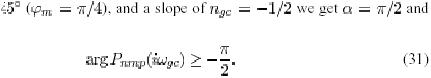 This gives the simple rule that the phase lag of the minimum phase components should be less than 90 at the gain criossover frequency.
4.2 A Zero in the Right Half Plane
We will now discuss limitations imposed by right half plane zeros. We will first consider systems with only one zero in right half plane. The non- minimum phase part of the plant transfer function then becomes
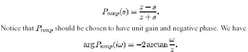
A right half plane zero gives an upper bound to the achievable bandwidth. The bandwidth decreases with decreasing frequency of the zero. It is thus more difficult to control system with slow zeros.
4.3 Time Delays
The transfer function for such systems has an essential singularity at infinity. The non-minimum phase part of the transfer function of the process is
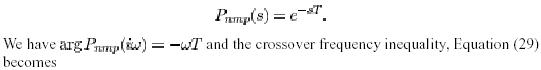

Time delays thus give an upper bound on the achievable bandwidth.
4.3 A Pole in the Right Half Plane
Consider a system with one pole in the right half plane. The non-minimum phase part of the transfer function is thus
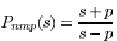
Where p>0. notice that the transfer function is normalized so that p has unit gain and negative phase. We have
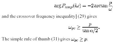
Unstable poles give a lower bound on the crossover frequency. For systems with right half plane poles the bandwidth must thus be sufficiently large.
4.4 Poles and zeros in the Right Half Plane Consider a system with

This simple rule of thumb (31) gives z>_25.3p table 1 gives the phase margin as a function of the ratio z/p for = /4 and =-1/2. The phase- margin that can be achieved for a given ratio p/z is
When the unstable zero is faster than the unstable pole, i.e. z > P the ration z/P thus must be sufficiently large in order to have the desired phase margin. The largest gain crossover frequency is the geometric mean of the unstable pole and zero.
|


