| An Introduction To Circuit Analysis |
Solving The Node Voltage Equations
Given these two equations:
Vx(1/Ra+
1/Rb + 1/Rc) -Vy/Rc
= Vs/Ra
-Vx/Rc+
Vy(1/Rc+ 1/Rd) = 0
One possible approach to solving these
equations is back substitution. The method of back substitution is fairly
simple in concept although you will need to be careful with details in the
execution of the algorithm. Here is the process.
- Solve an equation for one of
the unknowns.
- You can pick any equation
you want, but pick one.
- You will get an expression
for the chosen unknown that involves the rest of the unknowns and the
circuit parameters.
- Then, plug your expression
for the chosen unknown into all of the other equations wherever the chosen
unknown appears.
- Vx(1/Ra+
1/Rb + 1/Rc) -Vy/Rc
= Vs/Ra
- -Vx/Rc+
Vy(1/Rc+ 1/Rd) =
0
- In this set of
equations, we are going to solve the second (lower) equation for
Vx.
Doing that, we get:
- Now, we can take this
expression forVx
and use it in the first (top) equation. Doing that we get:
- VyRc(1/Rc+
1/Rd)*(1/Ra+ 1/Rb
+ 1/Rc) - Vy/Rc =
Vs/Ra
- This equation can be
solved easily forVy.
Collect all the terms on the left hand side and solve.
- Vy = Vs/[Ra/Rc(1/Rc+
1/Rd)*(1/Ra+ 1/Rb
+ 1/Rc)-1/Rc]
This can be simplified even further. You can
simplify this further, and we'll leave that to you.
Given a set of equations arising from
applying the node voltage method, there are several solution options. So far we
can see the following.
- With one unknown node
voltage, one equation results and it can be solved easily.
- With two unknown node
voltages, two equations result, and they can be solved with the method of
back substitution.
- With three unknown node
voltages, three equations would result. We could use back substitution to
eliminate one of the variables, getting two equations, then use back
substitution again to get to one variable and solve. It looks and sounds
messy, but we could do it.
Or, would it be better to look at more
general methods? There are other methods we could conceivably use. Let's think
about the kind of equations we have to deal with.
- As long as we have linear
resistors - and no diodes, transistors, etc. - we will always get a set of
simultaneous linear equations when we write the node equations.
- Back substitution is a
well-known way of solving sets of linear equations, but other methods based
on determinants and matrices are widely used.
- Many mathematical analysis
packages - like Mathcad and Matlab, for example - have built-in routines for
solving sets of simultaneous linear equations. If we want to use methods
based on determinants and matrices, and especiallly if we want to use the
packages available, we will need to be able to represent our node equations
in a way that is different.
- We need to be able to
represent our equations in a vector-matrix format.
Let's re-visit the equations for the ladder
network. Here they are again.
- Vx(1/Ra+
1/Rb + 1/Rc) -Vy/Rc
= Vs/Ra
- -Vx/Rc+
Vy(1/Rc+ 1/Rd) = 0
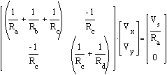
A
vector-matrix representation
that contains the same information is given below.


The vector-matrix formulation has several
important characteristics.
- The information about
the circuit connections are contained in a matrix that has numerous
reciprocal resistance values. Actually, they are conductances, and this
matrix is called theconductance matrix.
- The unknown node
voltages are represented as components in a
voltage vector.
- The voltage source gets
embedded in a source vector on the right hand side of the vector-matrix
equation for the circuit.
The vector-matrix formulation has the general
form:
G * v = I
- The matrix,
G, is the
conductance matrix. It
has units of ohms-1.
- The vector,
v, is the
node voltage vector. It
has units of volts.
- The vector,
I, is the
source vector. It has
units of current.
To solve for the voltage vector is simple in
principle. One only needs the inverse of the conductance
matrix.
v = G-1*I
Getting it is another story. How many ways do you
know to take the inverse of a matrix? How do you invert a matrix? Let us count
the ways.
- The inverse of a
matrix,G, is
given by:
- Adj(G)T/|G|
so, you can compute an inverse by hand.
- Mathcad and Matlab have
matrix inversion functions. Use them.
Well, that's two or three ways. Here is the inverse
and the circuit.


We wanted to show you this first because
we wanted to build a case that it may not be a good idea to compute this inverse
symbolically by hand. This is not a large circuit, and the analytic inverse
looks fairly horrendous.
- Even a circuit as
simple as this points to the fact that numerical solutions to circuits are
very important. In turn, that implies the you need to be familiar with
numerical ways to solve the kinds of equations that come out of linear
circuits. That meansyou need to understand
the algorithms and
you need to be able to use those algorithms
in various incarnations especially as they appear in analysis applications
like Mathcad and Matlab.
Before we do, there are some things we need
to point out about the conductance matrix.
- Ra,
Rb
andRc
are all attached to the first node, whereVx
appears.
- In the conductance
matrix, the reciprocals of all those resistances are added together to
give element (1,1).
- Similarly,
Rd
are attached to the second node, and their reciprocals are added to give
element (2,2) in the conductance matrix.
- Finally, note that
Rc
is shared between the two nodes, and the negative reciprocal of
Rc
appears in elements (1,2) and (2,1) in the conductance matrix.
It should be clear that there's a pretty
slick way to fill in a conductance matrix in the rules above. Review that
material to be sure you understand it. You can always write down a conductance
matrix from a circuit by following these two rules.
- If you have a resistance
between two nodes, node m and node n,
- Then that resistance
contributes a term that is the nevative reciprocal of the resistance to
the (n,m) entry in the conductance matrix, and to the (m,n) entry in the
conductance matrix.
- All such contributions
are added together.
- If you have a resistance
attached to node n,
- Then that resistance
makes a positive contrbution to the (n,n) entry.
That's it. At this point, you are invited to
check those results for this circuit.
Example
E1
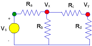
Here is a small ladder network.

And, here is the conductance
matrix equation for the circuit above. Notice how the conductance matrix is
built up from the conductances attached to each node using the method we
outlined above.

Determining the node voltages for this
circuit involves more than just the conductance matrix. The complete set of
equations is given again. We have an algorithm for determining the conductance
matrix on the left hand side of this equation, but we also need a way to
determine the right hand side. We are lucky in this circuit because the one
voltage source has one end connected to ground. That leads to a simple
expression on the right hand side of the set of equations.
When we have a voltage source with one end
connected to ground, then the right hand side of the circuit equation set takes
on a particularly simple form.
- The voltage source
appears in the equation for any node with which it shares a resistor. In
the example circuit,Vs
sharesRa
with the first node -Vx.
The voltage source appears on the right hand side of the equation for this
node, being multipled by the reciprocal of the shared resistance.
|

