| Frequency Dependent Circuits |
sin(x+y) = sin(x)cos(y)
+ cos(x)sin(y)
vin(t)
= B(RCwcos(wt) + sin(wt))

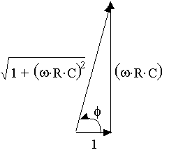
We need to refer to a little geometrical
construction - at the right. "Clearly" we have the relationships indicated
below for cos(f)
and sin(f)
 
So, now we can write:

Which reduces to:

There are two conclusions to draw from the
resulting expression for the input voltage.

-
The output voltage lags the
input voltage by a phase angle, f.

You can
use the expressions for the gain, B/A, and the
phase shift, f ,
to predict behvarior of circuits like this. You should note the following
in these expressions.
With those thoughts you can think a little more
deeply using the simulator we have just below.
A Simulation
of the Circuit
Note:
- This simulator is real time. However, to let you see how the circuit
behaves, we have made the signals very slow - on the order of a few Hertz, or
even a fraction of a Hertz. The time constant (the R-C product) should be
correspondingly long - on the order of a second (from a fraction of a second to
a few seconds). You won't see much if you stray far from these limits -
even though these are long time constants and the bandwidths are quite low.
That's just for purposes of illustration. (However, note that you could
get a one second time constant using R = 1.0 MW,
and C = 1.0mf.)
Here is the simulator.
Using this simulator, you
can do the following.
Reflections
In this lesson you have been introduced to a simple frequency dependent circuit.
We have used a very brute-force method - assuming a voltage at the output and
chasing that back to the input. That worked here, but it won't work
everywhere. Moreover, this is not the easiest way to make such
predictions, and before you attempt more complex circuits you should learn a
better way to analyze frequency dependent circuits. You need to learn
about
impedance
and
phasors. There are links below that will take you to many other
topics.
|

