Notice how this expression does not include any terms for the elevation or
orientation (z1 or z2) of the
Venturimeter. This means that the meter can be at any convenient angle to
function.
The purpose of the diffuser in a Venturi meter is to assure gradual and
steady deceleration after the throat. This is designed to ensure that the
pressure rises again to something near to the original value before the Venturi
meter. The angle of the diffuser is usually between 6 and 8 degrees. Wider than
this and the flow might separate from the walls resulting in increased friction
and energy and pressure loss. If the angle is less than this the meter becomes
very long and pressure losses again become significant. The efficiency of the
diffuser of increasing pressure back to the original is rarely greater than 80%.
4. Flow Through A Small
Orifice
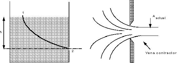
We are to consider the flow from a tank through a hole in the side close to
the base. The general arrangement and a close up of the hole and streamlines are
shown in the figure below

Tank and streamlines of flow out of the sharp edged orifice
The shape of the holes edges are as they are (sharp) to minimise frictional
losses by minimising the contact between the hole and the liquid - the only
contact is the very edge.
Looking at the streamlines you can see how they contract after the orifice to
a minimum value when they all become parallel, at this point, the velocity and
pressure are uniform across the jet. This convergence is called the vena
contracta. (From the Latin 'contracted vein'). It is necessary to know the
amount of contraction to allow us to calculate the flow.
We can predict the velocity at the orifice using the Bernoulli equation.
Apply it along the streamline joining point 1 on the surface to point 2 at the
centre of the orifice.
At the surface velocity is negligible (u1 = 0) and the
pressure atmospheric (p1 = 0).At the orifice the jet is open
to the air so again the pressure is atmospheric (p2
= 0). If we take the datum line through the orifice then z1 =
h and z2 =0, leaving

This is the theoretical value of velocity. Unfortunately it will be an over
estimate of the real velocity because friction losses have not been taken into
account. To incorporate friction we use the coefficient of velocity to
correct the theoretical velocity,

Each orifice has its own coefficient of velocity, they usually lie in the
range( 0.97 - 0.99)
To calculate the discharge through the orifice we multiply the area of the
jet by the velocity. The actual area of the jet is the area of the vena
contracta not the area of the orifice. We obtain this area by using a
coefficient of contraction for the orifice

So the discharge through the orifice is given by

Where Cd is the coefficient of discharge, and Cd
= Cc Cv
5. Time for a Tank to Empty
We now have an expression for the discharge out of a tank based on the height
of water above the orifice. It would be useful to know how long it would take
for the tank to empty.
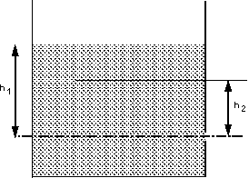
As the tank empties, so the level of water will fall. We can get an
expression for the time it takes to fall by integrating the expression for flow
between the initial and final levels.

Tank emptying from level h1 to h2.
The tank has a cross sectional area of A. In a time dt the
level falls by dh or the flow out of the tank is

(-ve sign as dh is falling)
Rearranging and substituting the expression for Q through the orifice
gives

This can be integrated between the initial level, h1, and
final level, h2, to give an expression for the time it takes
to fall this distance
|

