
For vertical walls of constant width it is usually much easier
to find the resultant force and centre of pressure. This is done graphically by
means of a pressure diagram.
Consider the tank in the diagram below having vertical walls
and holding a liquid of density
 to a
depth of H. To the right can be seen a graphical representation of the
(gauge) pressure change with depth on one of the vertical walls. Pressure
increases from zero at the surface linearly by to a
depth of H. To the right can be seen a graphical representation of the
(gauge) pressure change with depth on one of the vertical walls. Pressure
increases from zero at the surface linearly by
 , to a
maximum at the base of , to a
maximum at the base of
 . .
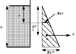
Pressure diagram for vertical wall.
The area of this triangle represents the resultant force
per unit width on the vertical wall, using SI units this would have units of
Newtons per metre. So
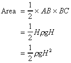
Resultant force per unit width

The force acts through the centroid of the pressure diagram.
For a triangle the centroid is at 2/3 its height, i.e. in the figure above the
resultant force acts horizontally through the point
 . .
For a vertical plane the depth to the centre of pressure is
given by

This can be checked against the previous method:
The resultant force is given by:

and the depth to the centre of pressure by:

and by the parallel axis theorem (with width of 1)
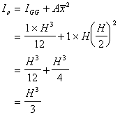
Giving depth to the centre of pressure

These two results are identical to the pressure diagram
method.
The same pressure diagram technique can be used when
combinations of liquids are held in tanks (e.g. oil floating on water) with
position of action found by taking moments of the individual resultant forces
for each fluid. Look at the examples to examine this area further.
More complex pressure diagrams can be draw for non-rectangular
or non-vertical planes but it is usually far easier to use the moments method.
As stated above, if the surface is curved the forces on each
element of the surface will not be parallel and must be combined using some
vectorial method.
It is most straightforward to calculate the horizontal and
vertical components and combine these to obtain the resultant force and its
direction. (This can also be done for all three dimensions, but here we will
only look at one vertical plane).
In the diagram below the liquid is resting on top of a curved
base.
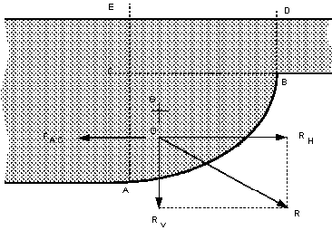
The element of fluid ABC is equilibrium (as the fluid is at
rest).
Horizontal forces
Considering the horizontal forces, none can act on CB as there
are no shear forces in a static fluid so the forces would act on the faces AC
and AB as shown below.
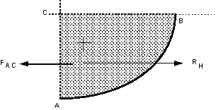
We can see that the horizontal force on AC,
 , must
equal and be in the opposite direction to the resultant force , must
equal and be in the opposite direction to the resultant force
 on
the curved surface. on
the curved surface.
As AC is the projection of the curved surface AB onto a
vertical plane, we can generalise this to say
The resultant horizontal force of a fluid above a curved
surface is:
RH =
Resultant force on the projection of the curved surface onto a vertical plane.
We know that the force on a vertical plane must act
horizontally (as it acts normal to the plane) and that
 must
act through the same point. So we can say must
act through the same point. So we can say
RH acts
horizontally through the centre of pressure of the projection of
the curved surface onto an vertical plane.
Thus we can use the pressure diagram method to calculate the
position and magnitude of the resultant horizontal force on a two dimensional
curved surface.
Vertical forces
The diagram below shows the vertical forces which act on the
element of fluid above the curved surface.

There are no shear force on the vertical edges, so the
vertical component can only be due to the weight of the fluid. So we can say
The resultant vertical force of a fluid above a curved surface
is:
RV = Weight of
fluid directly above the curved surface.
and it will act vertically downward through the centre of
gravity of the mass of fluid.
Resultant force
The overall resultant force is found by combining the vertical
and horizontal components vectorialy,
Resultant force

And acts through O at an angle of
 . .
The angle the resultant force makes to the horizontal is

The position of O is the point of integration of the
horizontal line of action of
 and
the vertical line of action of and
the vertical line of action of
 . .
What are the forces if the fluid is below the curved
surface? This situation may occur or a curved sluice
gate for example. The figure below shows a situation where there is a curved
surface which is experiencing fluid pressure from below.

The calculation of the forces acting from the fluid below is
very similar to when the fluid is above.
Horizontal force
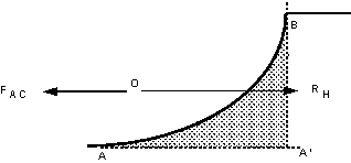
From the figure below we can see the only two horizontal
forces on the area of fluid, which is in equilibrium, are the horizontal
reaction force which is equal and in the opposite direction to the pressure
force on the vertical plane A'B. The resultant horizontal force, RH
acts as shown in the diagram. Thus we can say:
The resultant horizontal force of a fluid below a curved
surface is:

Vertical force
The vertical force are acting are as shown on the figure
below. If the curved surface were removed and the area it were replaced by the
fluid, the whole system would be in equilibrium. Thus the force required by the
curved surface to maintain equilibrium is equal to that force which the fluid
above the surface would exert - i.e. the weight of the fluid.
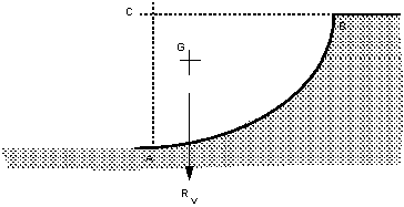
Thus we can say:
The resultant vertical force of a fluid below a curved surface
is:
Rv =Weight of the
imaginary volume of fluid vertically above the curved surface.
The resultant force and direction of application are
calculated in the same way as for fluids above the surface:
Resultant force

And acts through O at an angle of
 . .
The angle the resultant force makes to the horizontal is

|

